2-18
※
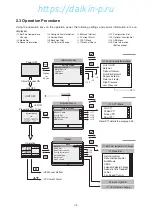
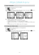
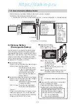
15 Data Information (Battery Mode)
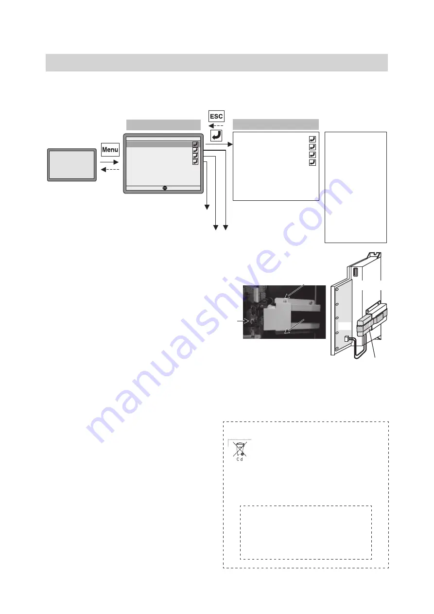
Data Information is available in battery mode when no power is supplied.
Furthermore, the following four items can be set :
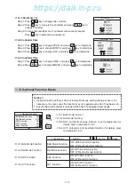
1. Unit ON/OFF OFF
⇔
ON
2. Temperature Setpoint
3. Defrost Interval Set
4. Humidity Setpoint
No key
operation
for 30 sec.
Power OFF
※
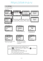
15 Data Information
[ Battery Mode ]
※
14 USB Menu
※
9 Alarm Display
Battery Mode
Alarm Record
Trip Chart
Data Information
USB Menu
※
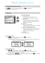
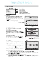
5-1 Trip Chart
Unit On/Off
Setpoint
Defrost Interval
Humidity Setpoint
Supply air temp
Return air temp
High Pressure
Low Pressure
USDA 1 Temp
USDA 2 Temp
USDA 3 Temp
Cargo Temp
Ventilation Volume
Battery Voltage
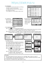
PTI History
1 Full
--Y,M,D--
2 Short
--Y,M,D--
3 Chilled --Y,M,D--
4 Frozen --Y,M,D--
5 Short
--Y,M,D--
Controller S/N
Controller Date
Controller Time
Software Ver.
2.4 Wake-up Battery
(Rechargeable Battery)
If power supply is not available, the above battery
mode will supply power from the wake-up battery
(rechargeable type) which is installed at CPU board.
Battery life is approximately 2 years. The remaining
voltage at normal time can be checked by battery
mode or during operation (*3 Sensor Information in
paragraph 2.3). The guide is as follows.
●
The remaining voltage
DC7.6V or more: The battery has been charged.
DC7.5V or less: Recharge battery.
To recharge, power the unit for
14 hours or more. When power
is being supplied, recharging
will be carried out while the
unit is operating and while it is
stopped (CB on).
●
The remaining voltage after completion of recharging
DC7.6V or more: The battery has been charged.
DC7.5V or less: The battery may have
deteriorated. It is recommendable
to replace the battery.
DC7.1V or less: The battery has deteriorated.
The battery must be replaced.
Caution !!
In case of using the battery for 2 years or more,
USDA data logging etc., may not be executed
even if LCD screen indicates that the remaining
voltage is more than DC7.6V or more.
●
Replacement of battery
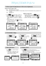
Battery is fixed on CPU
board. (Refer to the right fig.)
Step 1. Disconnect the
connecting cable
to CPU board from
connector. (X2A)
Step 2. Remove the mounting bolts of the
battery cover.
Step 3. Remove the Velcro tape and dismount
the battery together with lead wire.
Notice !!
This battery is Nickel-metal hydride battery.
●
Please send the used battery to our certified
stores or satellite parts center.
Please send the battery replaced in EU
member nation to the following address.
DAIKIN REFRIGERATION OFFICE
Fascinatio Boulevard 562, Cappele
A/D Ijssel 2909 VA, The Netherlands
Tel. +31-(0)10-286-2090
Fax. +31-(0)10-286-2099
X2A
X2A
Wake-up
battery
CPU board
02章01-18̲LX10F11B3̲TR16-02̲En.indd 2-18
02章01-18̲LX10F11B3̲TR16-02̲En.indd 2-18
2016/02/03 16:14:39
2016/02/03 16:14:39
https://daikin-p.ru
Summary of Contents for LX10F11B3
Page 7: ...https daikin p ru ...
Page 83: ...https daikin p ru ...
Page 93: ...https daikin p ru ...
Page 121: ...https daikin p ru ...
Page 129: ...https daikin p ru ...
Page 138: ...6 9 6 6 Sequence AIR WATER COOLED AIR WATER COOLED https daikin p ru ...
Page 139: ...6 10 Stereoscopic wiring diagram AIR WATER COOLED https daikin p ru ...

