4-1
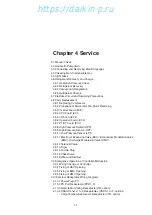
Chapter 4 Service
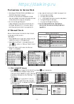
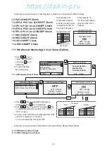
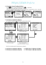
4.1 Manual Check
4.2 Automatic Pumpdown
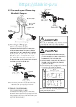
4.3 Connecting and Removing Manifold gauges
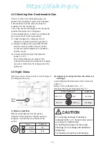
4.4 Checking Non-Condensable Gas
4.5 Sight Glass
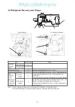
4.6 Refrigerant Recovery and Charge
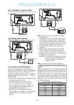
4.6.1 Operation Pressure Check
4.6.2 Refrigerant Recovery
4.6.3 Vacuum and Dehydration
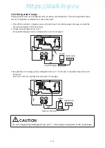
4.6.4 Refrigerant Charge
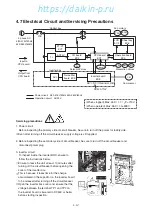
4.7 Electrical Circuit and Servicing Precautions
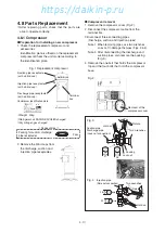
4.8 Parts Replacement
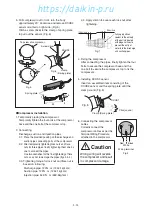
4.8.1 Replacing Compressor
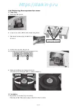
4.8.2 Procedure of Evaporator Fan Motor Removing
4.8.3 Inverter board (EC8)
4.8.4 CPU board (EC1)
4.8.5 I/O board (EC2)
4.8.6 Operation board (EC3)
4.8.7 PT/CT board (EC7)
4.8.8 High Pressure Switch (HPS)
4.8.9 High Pressure Sensor (HPT)
4.8.10 Low Pressure Sensor (LPT)
4.8.11 Electronic Expansion Valve (EEV), Economizer Modulation Valve
(EMV), Discharge Modulation Valve (DMV)
4.8.12 Solenoid Valve
4.8.13 Dryer
4.8.14 Fusible Plug
4.8.15 Check Valve
4.8.16 Filter and Strainer
4.9 Emergency Operation at Controller Malfunction
4.9.1 Wiring Change of Controller
4.9.2 Fixing of EEV Opening
4.9.3 Fixing of EMV Opening
4.9.4 Fixing of DMV Opening
4.10 External Receptacle Wiring Diagrams
4.10.1 Power Plug (P1)
4.10.2 PC Port Receptacle (PPR1, 2)
4.10.3 Remote Monitoring Receptacle (RM; option)
4.10.4 USDA Sensor 1 to 3 Receptacles (USDA 1 to 3; options)
Cargo Temperature Sensor Receptacle (CTR; option)
04章̲LX10F11B3̲TR16-02̲En.indd 4-1
04章̲LX10F11B3̲TR16-02̲En.indd 4-1
2016/02/03 16:21:57
2016/02/03 16:21:57
https://daikin-p.ru
Summary of Contents for LX10F11B3
Page 7: ...https daikin p ru ...
Page 83: ...https daikin p ru ...
Page 93: ...https daikin p ru ...
Page 121: ...https daikin p ru ...
Page 129: ...https daikin p ru ...
Page 138: ...6 9 6 6 Sequence AIR WATER COOLED AIR WATER COOLED https daikin p ru ...
Page 139: ...6 10 Stereoscopic wiring diagram AIR WATER COOLED https daikin p ru ...

