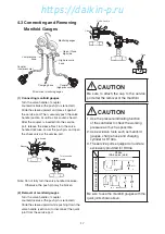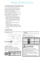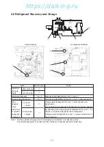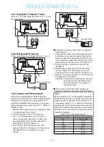
4-5
NEXT
PREV
2/3
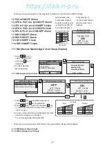
FA Calibration
200 mm
Manual Check
Step 1. Fully open Ventilation
cover
Step 2. Close ventilation
cover to zero point
Step 4 : Press ENTER
Manual Check
3 mm
ESC : Cancel
FA opening 0 mm
after calibration
NEXT
PREV
2/3
FA Calibration
0 mm
Manual Check
2/3
2/3
Complete
0mm
ESC : Return
Manual Check
②
Set ventilation
volume.
①
Fully open
●
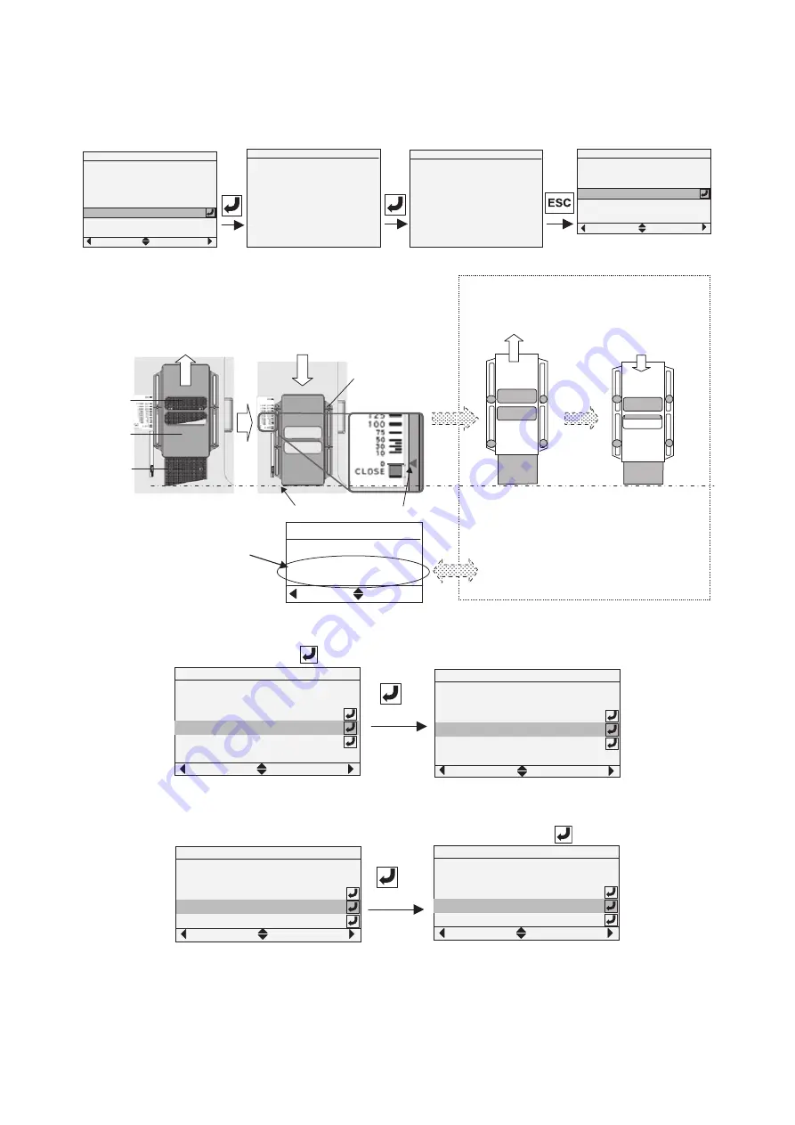
After completing calibration,
set ventilation volume.
①
Fully open ventilation cover
②
Move the cover down. When the ventilation volume display
reaches the setting value, tighten the four wing bolts.
Note: If you move the cover up while configuring the
setting, perform the procedure again from step
①
.
Ventilation volume is confirmed in the display
according to
*
3 Sensor Information or battery
mode of
*
15 Data Information in paragraph 2.3.
Setting value of
ventilation volume
Sensor Information
PREV
50 m3/h
Ventilation Volume
3/3
FA intake
air hole
Ventilation
cover
FA outlet
Wing bolt
Step 1.
Fully open
Step 2.
While closing the cover, adjust to the zero
position of the ventilation identification plate,
and then tighten the four wing bolts.
Zero adjustment position
※
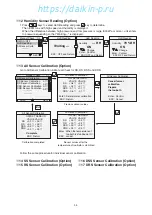
18 FA Calibration (Option)
Go to FA Calibration in Manual Check first, then set ventilation volume.
※
19 Trip Start Time
Go to Trip Start reset by pressing
key for 3 seconds.
※
20 Comp. Running Hrs
1. Current Compressor Running Hrs is 1000 Hr as example below.
2. When compressor is replaced, it's recommended to reset 0 Hr by pressing
key for 3 seconds.
Follow the same procedure for EFH, EFL, CFH and CFL running hrs.
※
21 EFH Running Hrs
※
22 EFL Running Hrs
※
23 CFH Running Hrs
※
24 CFL Running Hrs
NEXT
PREV
2/3
3mm
FA Calibration
Trip Start Time
Comp Running Hrs
1000Hr
7Day12Hr
Manual Check
3 seconds
NEXT
PREV
2/3
3mm
FA Calibration
Trip Start Time
Comp Running Hrs
1000Hr
0Hr
Manual Check
NEXT
PREV
2/3
Trip Start Time
Comp Running Hrs
EFH Running Hrs
1000Hr
600Hr
7Day12Hr
Manual Check
NEXT
PREV
2/3
Trip Start Time
Comp Running Hrs
EFH Running Hrs
0Hr
600Hr
7Day12Hr
Manual Check
3 seconds
04章̲LX10F11B3̲TR16-02̲En.indd 4-5
04章̲LX10F11B3̲TR16-02̲En.indd 4-5
2016/02/03 16:22:00
2016/02/03 16:22:00
https://daikin-p.ru
Summary of Contents for LX10F11B3
Page 7: ...https daikin p ru ...
Page 83: ...https daikin p ru ...
Page 93: ...https daikin p ru ...
Page 121: ...https daikin p ru ...
Page 129: ...https daikin p ru ...
Page 138: ...6 9 6 6 Sequence AIR WATER COOLED AIR WATER COOLED https daikin p ru ...
Page 139: ...6 10 Stereoscopic wiring diagram AIR WATER COOLED https daikin p ru ...

