background image

113

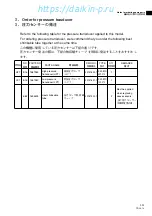
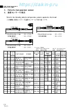
(TR06-13)

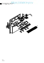
Measuring and adjusting tools

測定調整用工具

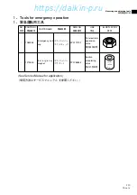
1.Tools for emergency operation
1.緊急運転用工具

(See Service Manual for application.)

(使用方法はサービスマニュアルを参照ください。)

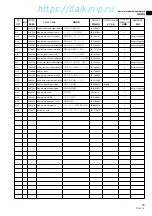
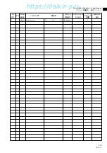
NO.

符号

PARTS NO.

部品番号

PARTS NAME

部品名称

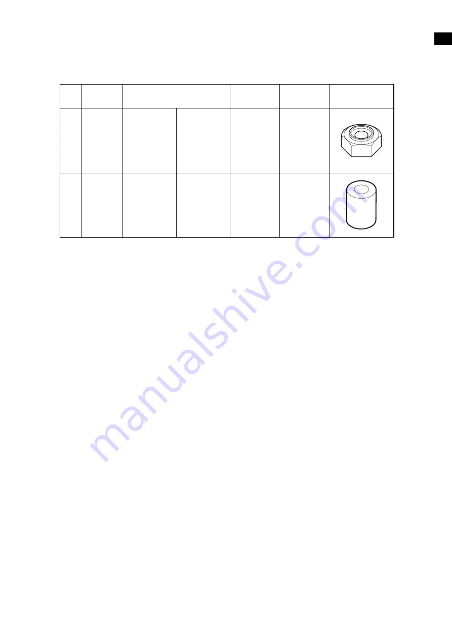
ILLUSTLATION

姿図

-

1270530

E m e r g e n c y

magnet

エマージェンシー
マグネット

-

1080263

Emergency coil

cap

エマージェンシー
コイルキャップ

DWG NO.

図面番号

USE

用途

3P017370-1

For electronic

expansion

valve

電子膨張弁用

2P078385-2

Suction

modulating

valve

吸入比例弁用

UPS

I

DE

O

PEN

DO

WN

S

I

D

E

108-115̲PL(LXE10E-1E)    2007.05.02  11:30    ページ  113

https://daikin-p.ru

Summary of Contents for LXE10E-1

Page 1: ...Marine type Container Refrigeration Unit TR06 13 LXE10E 1E Service Manual Parts List Optional Functions https daikin p ru...

Page 2: ...XE10E 1B LXE10E 1C LXE10E 1D Fitted Not fitted Not fitted Not fitted SPCH01 SPCH01 NSK BC030F NSK BC030F SPCL02 SPCL02 NSK BC010F NSK BC010F Left side of compressor Left side of compressor Right side...

Page 3: ...cer characteristics table 7 5 7 10 Low pressure transducer characteristics table 7 5 7 11 Piping diagram 7 6 7 12 Pilot lamps 7 7 7 13 Fuse protection table 7 8 7 14 Schematic wiring diagram 7 10 7 15...

Page 4: ...r on demand defrost and manual switch Detecting the temperature of evaporator outlet pipe and return air Electronic expansion valve Capacity control Capacity control with hot gas bypass and suction mo...

Page 5: ...Discharge gas by pass solenoid valve BSV 1 Defrost solenoid valve DSV 2 Economizer solenoid valve ESV 3 Electronic expansion valve EV 4 Hot gas solenoid valve HSV 5 Injection solenoid valve ISV 6 Liq...

Page 6: ...egulator Valve EV Electronic Expansion Valve ESV Economizer Solenoid Valve ISV Injection Solenoid Valve LSV Liquid Solenoid Valve RSV Reheater Solenoid Valve for dehumidification control SMV Suction M...

Page 7: ...ollows For details refer to section 3 1 to 3 4 Operation mode Software version Setting temperature Control sensor Operation description Frozen mode 2403 30 0 5 1 22 0 22 8 Return air temperature senso...

Page 8: ...ss solenoid valve BSV OFF OFF OFF Capillary solenoid valve 4 CSV OFF OFF OFF Suction modulating valve SMV 100 Electronic expansion valve EV 10 to 100 Note 1 High pressure control 2 Injection control R...

Page 9: ...r runs for at least 2 minutes every time once it is turned on Even if the control temperature becomes SP or lower point C within 2 minutes after the compressor is turned on the compressor condenser fa...

Page 10: ...ction modulating valve SMV 12 to 100 1 3 to 100 100 100 Electronic expansion valve EV 10 to 100 10 to 100 0 50 2 5 2 Chilled mode Control state transition and common control START SS SP 1 5 C SS SP 1...

Page 11: ...The control temperature converges to the set point temperature point e while repeats temperature increasing and decreasing During capacity control hot gas by pass HSV DSV BSV and liquid injection ISV...

Page 12: ...OFF 1 Liquid solenoid valve LSV OFF OFF Economizer solenoid valve ESV ON OFF 4 OFF Injection solenoid valve ISV OFF ON 5 ON OFF 2 Hot gas solenoid valve HSV OFF ON Defrost solenoid valve DSV OFF ON Di...

Page 13: ...of the in range 1 Refer to 3 On demand defrost 2 6 hours when the control temperature is 20 C or below wStarting by MANUAL DEFROST key on the operation panel sheet key Press the MANUAL DEFROST key the...

Page 14: ...ns for 30 min or later after startup listed in Table above regardless of operating time w90 minutes have elapsed eAny one of protective devices is activated Note CSV is fitted only for LXE10E 1 but no...

Page 15: ...ification controller setting is required Refer to Page 3 12 In dehumidification the Reheat Solenoid Valve RSV Capillary Solenoid Valve CSV Note opens to give high pressurized refrigerant to reheat coi...

Page 16: ...ly alarm display E315 PT CT board failure Restart after 3 minutes E401 Supply air temperature sensor SS malfunction Back up operation E402 Data recorder supply air temperature sensor DSS malfunction B...

Page 17: ...CD display Display Temperature on the return air sensor Temperature on the supply air sensor Setting change Inside temperature defrosting interval dehumidifying set Optional Unit ON OFF 2 USDA data lo...

Page 18: ...M R H When the pump down operation is ended abnormally E201 pump down malfunction will be displayed When the pump down operation is completed the unit stops state COMP DEFROST IN RANGE DE HUMID SUPPLY...

Page 19: ...ll close Termination GOOD Pump down start Compressor stops at LP 55kPa Compressor continues to stop for 20 seconds COMP ON ON OFF OFF OFF LSV ON EV ON ON ON ON ON full close SMV ON ON ON ON ON ESV ON...

Page 20: ...rging t e After cavuuming charge liquid refrigerant from t first and then from e If not reached to the specified amount 5 4kg go to next below 1 Operate Automatic Pump Down first and stop it using ON...

Page 21: ...he unit after collecting the refrigerant into the liquid receiver Run the condenser fan by using the condenser fan check see page 3 56 in the manual check functions and wait untill the condenser cooli...

Page 22: ...circuit in the vacuum state However if air enters in the refrigerant circuit vacuum up the circuit to 76cmHg and then vacuum the circuit for another 2 hours or more b Cylinder weight recording Place...

Page 23: ...cking the wiring once test run the system to verify that no trouble is found CAUTION Be sure that the main power is disconnected 4 2 4 Electronic expansion valve Model Coil EBM MD12DM 1 Body EDM B804D...

Page 24: ...n head bolt t Body Seal using with sillicon Sealant 4 2 5 Thermostatic expansion valve TEV Model VTX 3410DMS This is an internal equalizer type of thermostatic automatic expansion valve and installed...

Page 25: ...top of the coil to pull the coil out e Replace the coil with a new one and restore the hexagonal head bolt the binding band and connector on the original position When reassembling the coil the tight...

Page 26: ...time Otherwise the transducer may be damaged 4 2 12 Low pressure transducer LPT The LPT is located in the refrigerant circuit The operating low pressure value is displayed on the controller indicatio...

Page 27: ...ward w Binding band Sealer 4 2 14 Water pressure switch WPS Type LCB MB10 Set value OFF 98kPa at 1 0 kg cm2 pressure ON 39kPa at 0 4 kg cm2 pressure This switch is used to select air cooled operation...

Page 28: ...rator outlet tube long Insulation pipe cover of evaporator outlet sensor is improperly installed Evaporator outlet sensor is defective Defrosting solenoid valve does Lead wire breakage not open Coil b...

Page 29: ...n CPU board malfunction E423 Current sensor CT2 Sensor malfunction malfunction CPU board malfunction E425 Pulp temperature sensor Wrong wiring in the USDA receptacle E427 USDA1 to 3 malfunction Line b...

Page 30: ...r fan motor coil 19 4 LSV Liquid solenoid valve coil 15 2 1 1 common HSV ISV EV White Red 150 Orange Red 150 Yellow Brown 150 Blue Brown 150 SMV Suction modulation valve coil Blue Yellow 113 Black Whi...

Page 31: ...r LSV Liquid Solenoid Valve HSV Hot Gas Solenoid Valve DSV Defrost Solenoid Valve ISV Injection Solenoid Valve ESV Economizer Solenoid Valve BSV Discharge Gas Bypass Solenoid Valve WPS Water pressure...

Page 32: ...31 7 10 7 14 Schematic wiring diagram LXE10E 1E https daikin p ru...

Page 33: ...32 https daikin p ru...

Page 34: ...33 7 11 7 15 Stereoscopic wiring diagram LXE10E 1E https daikin p ru...

Page 35: ...34 https daikin p ru...

Page 36: ...2 2 5 4 24 4 23 2 2 5 EV 4 17 kg 2 1 LXE10E 1A LXE10E 1B LXE10E 1C LXE10E 1D SPCH01 NSK BC030F SPCL02 NSK BC010F 505 490 LXE10E 1 TR03 08 2406 3 33 2407 2 23 2404 2 16 5 0 10 0 E205 LXE10E 1E 485 htt...

Page 37: ...4 7 2 7 5 EV 7 2 7 6 HFC134a 7 3 7 7 SS RS DSS DRS RSS RRS EIS EOS SGS AMBS 7 4 7 8 DCHS 7 5 7 9 7 5 7 10 7 5 7 11 7 6 7 12 7 7 7 13 7 8 7 14 7 9 7 15 7 10 7 16 7 11 3 4 5 1 1 1 1 1 1 1 1 2 1 1 1 3 1...

Page 38: ...2 1 LXE10E DECOS d AC 3 380V 400V 415V 50Hz 440V 460V 60Hz 5 5kW 3 3 PT CT 10A 5A R134a 5 4 kg IDEMITSU Daphne hermetic oil FVC 46D 2 2 R LXE10E 1 1A 1B 505 kg LXE10E 1C 1D 490 kg 1E 485 kg https dai...

Page 39: ...6 7 8 9 0 BSV 1 DSV 2 ESV 3 EV 4 HSV 5 ISV 6 LSV 7 RSV 8 DPR 9 SMV 0 TEV 1 AMBS 2 DCHS 3 HPS 4 HPT 5 LPT 6 SGS 3 1 32 15 31 35 2 22 24 12 10 36 14 11 13 19 18 9 4 5 23 30 16 25 7 6 8 33 17 26 28 20 3...

Page 40: ...2 3 LXE10E 1A 1B 1C 1D 1E DSV RSV HSV BSV ESV ISV EV LPT HPT HPS DCHS w q r t AMBS CSSV SGS SMV LSV WPS e BSV CDSV CSSV DSV DPR EV ESV ISV LSV RSV SMV TEV AMBS DCHS HPS HPT LPT SGS WPS https daikin p...

Page 41: ...40 2 14 2 5 2 3 9 2 5 1 2 5 5 2403 30 0 5 1 22 0 22 8 ON OFF 2404 30 0 10 1 22 0 13 8 2403 5 0 30 0 23 0 86 0 2404 10 0 30 0 14 0 86 0 https daikin p ru...

Page 42: ...OFF 1 ON OFF 1 OFF LSV ON OFF OFF ESV ON OFF 3 ON OFF 3 OFF ISV OFF ON 2 OFF ON 2 OFF HSV OFF OFF OFF DSV OFF OFF OFF BSV OFF OFF OFF 4 CSV OFF OFF OFF SMV 100 EV 10 100 1 2 2 25 3 2 26 4 LXE10E 1 LXE...

Page 43: ...5 1 22 8 F ON OFF 2 q SP 1 0 A OFF SP 1 10 SP SP 2 SP 3 SP 1 A C OFF w SP ON 1 ON 2 ON 2 SP C OFF 2 EV HSV LSV ISV DSV BSV ESV LPT DPR HPT SMV HPS WPS CSV LXE10E 1 LXE10E 1A FROZEN Return air 5 C http...

Page 44: ...EFH ON ON ON ON EFL OFF OFF OFF OFF CF ON OFF 1 ON OFF 4 ON OFF 1 OFF LSV ON ON OFF OFF ESV ON OFF 5 OFF OFF OFF ISV ON OFF 2 ON OFF 4 ON OFF 3 OFF HSV OFF ON OFF 4 ON OFF DSV OFF ON OFF 4 ON OFF BSV...

Page 45: ...44 2 18 1 5 0 23 0 F 2 a 1 5 b ON HSV DSV BSV ISV c 1 5 1 5 d 3 3 2 1 1 2 SP 1 6 2 5 4 3 LXE10E 1 LXE10E 1A https daikin p ru...

Page 46: ...C ON ON EFH ON OFF 3 OFF EFL CF ON OFF 1 ON OFF 1 LSV OFF OFF ESV ON OFF 4 OFF ISV OFF ON 5 ON OFF 2 HSV OFF ON DSV OFF ON BSV OFF OFF RSV OFF OFF ON 6 7 CSV OFF OFF SMV 100 100 EV 10 100 5 1 2 3 EFL...

Page 47: ...46 2 20 1 2 5 20 q 4 2 3 6 9 12 24 99 1 4 2 4 30 30 1 12 6 2 20 6 w LED ON e 0 2 1hr 20 3 99 SP 5 1 12 6 1 1st 1hour T1 2 12 last 1hour T2 3 1 13 2 2 1 24 T2 T1 1 15 https daikin p ru...

Page 48: ...47 2 21 4 3 1 q 2407 2406 30 w90 e LXE10E 1 LXE10E 1A 30 EOS 30 or EIS 85 EOS 30 or EIS 85 30 EOS 30 or EIS 85 EOS 30 and RS DRS 15 or EIS 85 https daikin p ru...

Page 49: ...48 2 22 2 5 4 3 12 RSV CSV DEHUMID LED 1 30 RH 95 RH LXE10E 1 LXE10E 1A https daikin p ru...

Page 50: ...90kPa 3 E201 90 E203 3 SP 3 0 3 E205 E207 90 E303 SRAM E305 SRAM E307 SRAM E311 SRAM E315 PT CT 3 E401 SS E402 DSS E403 RS E404 DRS E405 DCHS E406 SGS E407 EIS E409 EOS E411 AMBS E413 LPT E415 HPT E41...

Page 51: ...50 3 36 3 5 3 5 1 CPU I O 3 5 2 1 3 3 2 3 11 LCD ON OFF 2 USDA log 1 USDA log USDA PTI 3 Trip log 1 Trip 3 5 3 https daikin p ru...

Page 52: ...ROST IN RANGE DE HUMID SUPPLY RETURN ALARM R H COMP DEFROST IN RANGE DE HUMID SUPPLY RETURN ALARM R H E201 COMP DEFROST IN RANGE DE HUMID SUPPLY RETURN ALARM R H 2 OFF LED LCD P DOWN ON P DOWN P DOWN...

Page 53: ...SV ON EV ON ON ON ON ON SMV ON ON ON ON ON ESV ON OFF DSV HSV ON 1 ISV ON 2 CSV HSV Compressor Reheat Coil BSV DSV CSV LSV ESV EV Evaporator RSV DPR Condenser Air Condenser Water Check valve SMV TEV I...

Page 54: ...pressor Reheat Coil ISV BSV CSV LSV ESV HSV EV Evaporator RSV Condenser Air Condenser Water SMV TEV Drier 4 5 4 1 4 Schematic diagram R134a 4 6kg 1 2 BSV DSV HSV ISV 3 5 4kg 1 OFF 2 LSV LXE10E 1 LXE10...

Page 55: ...54 4 6 1 2 P 4 3 P 3 56 3 L LP HP LXE10E 1 LXE10E 1A LXE10E 1 LXE10E 1A https daikin p ru...

Page 56: ...55 4 7 4 1 20kg HFC134a 2 3 50kg 4 a 76cmHg 76cmHg 2 b c 1 50 1 2 2 R134a L R134a LXE10E 1 LXE10E 1A LXE10E 1 LXE10E 1A LXE10E 1 LXE10E 1A https daikin p ru...

Page 57: ...CT1 CT2 CT1 CT2 2 3 4 OC LXE5C LXE10C LXE10D LXE10D LXE10E Dual 5HP Dual 10HP Single 10HP OC 8 5A 15A 26A J3 J2 J1 4 2 4 EBM MD12DM 1 EDM B804DM 1 6 4 1 LXE10E 1A 13 7 15 7N m 134 164kgf cm https dai...

Page 58: ...57 4 18 2 120 248 F EV EV 4 2 5 TEV VTX 3410DMS 1 120 248 F https daikin p ru...

Page 59: ...58 4 21 4 2 8 NEV 803DXF 1 NEV 202DXF 2 ESV NEV 202DXF NEV MOAB507C ISV LSV NEV 803DXF BSV DSV HSV RSV LXE10E 1 LXE10E 1A CSV 1 2 9N m 30kg cm 2 120 248 F https daikin p ru...

Page 60: ...3 4 2 11 HPS ACB KB15 OFF 2400kPa 24 47kg F ON 1900kPa 19 37kg F 1 HPS HPS 4 2 12 LPT 1 C LXE10E 1 1A LXE10E 1B B A C COMPRESSOR L P T H P T H P S D LXE10E 1 1A LXE10E 1B SPCL02 NSK BC010F https daiki...

Page 61: ...60 4 24 KE4898 4 2 13 HPT 1 4 2 14 WPS LCB MB10 OFF 98kPa 1 0kg cm2 ON 39kPa 0 4kg cm2 OFF 1 WPS WPS WPS 4 2 15 RH e t r q w WPS LXE10E 1 1A LXE10E 1B SPCH01 NSK BC030F https daikin p ru...

Page 62: ...61 6 7 E201 60 E203 SP 3 0 3 P E205 E207 90 E303 E305 SRAM CPU E307 E311 E401 SS E402 DSS E403 RS CPU E404 DRS CPU E405 DCHS CPU https daikin p ru...

Page 63: ...409 EOS CPU E411 AMBS CPU E413 LPT CPU E415 HPT CPU E417 PT1 CPU E419 PT2 CPU E421 CT1 CPU E423 CT2 CPU E425 USDA1 3 USDA E427 USDA E429 USDA CPU E431 HuS CPU E603 SMV CPU DECOS a b c d E607 CPU E707...

Page 64: ...10E 1 LXE10E 1A 7 4 CM 1 780 75 CFM 57 2 EFM 19 4 LSV 15 2 1 1 HSV ISV EV 150 150 150 150 SMV 113 113 DSV ESV BSV COM COM CSV 1 7 5 EV N m kgf cm Ibf ft 13 7 to 15 7 134 to 164 10 1 to 11 6 RSV https...

Page 65: ...Solenoid Valve HSV Hot Gas Solenoid Valve regulator DSV Defrost Solenoid Valve ISV Injection Solenoid Valve ESV Economizer Solenoid Valve BSV Discharge Gas Bypass Solenoid Valve WPS Water pressure swi...

Page 66: ...65 LXE10E 1E 7 10 https daikin p ru...

Page 67: ...66 https daikin p ru...

Page 68: ...67 LXE10E 1E 7 11 https daikin p ru...

Page 69: ...68 https daikin p ru...

Page 70: ...ed as a set so please contact with the nearest DAIKIN PARTS CENTRE 3 Index symbols Meaning of the ranking A B and C are as follows A The most important spare parts 1 The parts whose malfunction cause...

Page 71: ...E POWER 5 5 10 10 CONDENSER COOLING TYPE NIL AIR and WATER COOLED TYPE A AIR COOLED TYPE OPTION NUMBER L X E E 5 5 10 10 A Note R GIVEN AFTER OPTION NUMBER STANDS FOR REVISION AND IT IS GIVEN FOR THE...

Page 72: ...related with option 2 MODEM 102 MODEM K Parts related with option 3 Indoor fanguard 104 L List of size for standard pipe clamp 106 1 Resin clamp 2 Tube clamp 3 Cushion rubber for pipe clamp M Note for...

Page 73: ...42 A43 A44 A39 A35 A31 A32 A33 A36 A37 A48 A49 A38 A34 A18 A9 A8 E13 A1 A35 A31 A32 A33 A34 A14 A2 A3 A15 Refer to 109Page E55 A11 A10 A12 A6 A5 A47 A4 Refer to 108Page A19 A21 A22 A20 A40 A23 A22 A46...

Page 74: ...Page 109 A20 1266221 Sealing material ventilator 4P016185 1 2 Refer to Page 109 A21 1497924 Hexagon head bolt 4P048686 20 4 A29 1496820 Protection cover 2 4P085921 2 1 A38 1496851 Indicator window 4P1...

Page 75: ...PARTS NAME DWG NO TYPE SPECIFICATION QTY UNIT 1 REMARKS A48 1495074 Right packing 1 4P118216 1 1 A49 1495081 Right packing 2 4P118216 2 1 E13 1266788 Resin clamp NE41015 12 MILK WHITE 6 E55 1267077 Pa...

Page 76: ...Parts related with the unit outside TR06 13 75 NO INDEX PARTS NO PARTS NAME DWG NO TYPE SPECIFICATION QTY UNIT 1 REMARKS https daikin p ru...

Page 77: ...B4 4 B4 3 B27 B4 1 B4 1 1 B3 3 B4 B3 2 2 B3 2 1 B3 2 B4 3 B3 2 B8 B3 2 3 B4 3 2 B4 3 1 B4 3 B4 3 3 SMV B8 1 B11 B23 B13 B28 B9 B2 B14 B1 B25 B9 B9 1 B9 2 B9 3 B3 5 B3 5 1 B3 5 2 B3 5 3 B24 B4 6 B4 5...

Page 78: ...8737 2 1 B4 1 1493744 Water cooled condenser CU LXE10E 1 B4 1 1 A 1498035 Fusible plug 3SA27103 1 1 B4 1 2 258215 Water inlet joint R4713106 2 1 B4 1 3 1508127 Water outlet socket 3P121979 1 1 B4 3 C...

Page 79: ...ion modulating valve 2P078385 1 KO 2 B9 C 1494646 Stop valve ass y 3SA58059 1 1 B9 1 C 149782J Service valve cap 3SA58059 1 TO 1 B9 2 B 1497847 Service valve body 3SA58059 1 TE 1 B9 3 B 149786J Valve...

Page 80: ...Parts related with refrigerant piping outside TR06 13 79 NO INDEX PARTS NO PARTS NAME DWG NO TYPE SPECIFICATION QTY UNIT 1 REMARKS https daikin p ru...

Page 81: ...C1 1 C2 Option C12 Option C3 C6 C6 C5 C4 C19 C19 C23 C17 C29 C31 C30 C14 C35 C16 C10 C21 C9 C33 C32 C30 C29 C22 C28 E57 Detail of E57 PUTTY Equivalent of NEO SEAL B 1 Sealing compound KE44RTV or its...

Page 82: ...C19 1135978 Reinforce plate fan motor 4P011316 1 4 C21 1135125 Hinge 3P043374 1 1 C25 A 1375327 Sensor DSS 3PA61769 12 1 Refer to Page 112 C35 1496976 Rear plate middle fixture 4P105391 1 2 C37 16672...

Page 83: ...ng inside D6 D4 Detail of D4 D5 Detail of D5 45 45 E63 D5 E30 Feeler bulb inserting pipe Feeler bulb Feeler bulb D3 1 D3 10 D3 6 D3 2 D3 11 D3 2 D1 D3 4 D3 3 D2 B23 D4 E60 D8 D9 D3 5 D3 7 D3 D3 9 D3 8...

Page 84: ...nsulation tube 4P103439 1 1 D3 6 1380925 Thermal insulation tube 4P103439 2 1 D3 7 1380932 Thermal insulation tube 4P103439 3 1 D3 8 1380949 Thermal insulation tube 4P103439 4 1 D3 9 1549971 Thermal i...

Page 85: ...79 A7 E97 A Detail of A D Section D E View E B View B C View C 400V cable Compressor cable Compressor lead wire connection Feeler bulb inserting pipe Feeler bulb Discharge pipe Thermistor CTP Pink 132...

Page 86: ...il E16 E16 E100 E92 E19 L 50mm E1 E86 E88 E20 L 60mm E17 E8 E7 E34 E22 E104 E10 E84 E6 E22 E33 Drier E87 E87 E89 E31 L 60mm E29 ISV ESV pipe ass y Discharge pipe Liquid pipe ass y TEV capillary BSV ou...

Page 87: ...86 I View I Drain pan piping ass y fixing detail J View J E15 E23 E102 E103 E95 E94 E103 J I E79 E79 Other parts Pipe clamp sealing and insulation material etc TR06 13 https daikin p ru...

Page 88: ...Other parts Pipe clamp sealing and insulation material etc TR06 13 87 E53 E54 K Part K detail E42 E44 E39 E39 E42 E37 E46 E46 E38 E37 E41 E36 K https daikin p ru...

Page 89: ...valve feeler bulb EV inlet pipe Moisture indicator inlet pipe TEV outlet pipe ESV pipe ass y N Part N detail L View L SMV SMV insulation detail N E71 E69 E63 Other parts Pipe clamp sealing and insula...

Page 90: ...1 Page 85 E34 1270446 Dryer cushion rubber 4PA53083 2 1 Page 85 E44 1624308 Supply sensor cover sealing 4P154324 2 2 Page 87 E46 1605422 Side stay packing 4P095033 2 2 Page 87 E61 698506 Feeler bulb c...

Page 91: ...5347 1 1 Page 84 85 E87 B 1497070 Thermal insulation tape no dry 3SA90101 3 KA 3 Page 85 E88 1667297 LSV cover 4P164903 1 1 Page 85 E89 1270484 Mounting plate solenoid valve 4P082208 1 1 Page 85 E91 1...

Page 92: ...Other parts Pipe clamp sealing and insulation material etc TR06 13 91 NO INDEX PARTS NO PARTS NAME DWG NO TYPE SPECIFICATION QTY UNIT 1 REMARKS https daikin p ru...

Page 93: ...Control box F7 2 F7 1 F7 11 F7 10 F7 12 F7 3 F7 4 F7 7 F61 F7 5 F7 9 F7 8 F7 6 F4 F18 F30 F27 F59 F23 F24 F22 F58 F17 F33 F46 F25 F57 F59 F39 F7 F50 TR06 13 92 https daikin p ru...

Page 94: ...0 2 F70 3 F78 F19 F20 F28 F73 F77 F75 F76 F74 F6 F32 F3 F42 F62 F72 F71 F69 F68 F66 F48 F64 F63 F65 F67 F29 F26 F34 8 1 F34 8 F34 11 F44 F13 F45 F34 10 F31 1 F34 5 F34 6 F34 9 F31 F38 F37 F35 F40 F49...

Page 95: ...2P121587 1 1 F23 A 124149J Magnetic contactor Phase correction contactor 3P071508 3 24V RSK 35J 1 F31 A 1679137 Terminal strip boaed 2P174377 1 1 F32 1381144 Mounting plate thermal sensor 4P010921 1 1...

Page 96: ...F49 1136539 Clamp 4P015574 2 2 F64 1295647 Fixing plate for lever 4P085164 1 1 F65 0907125 Sealed sheet 4PA52417 1 t0 075 0 01 1 F66 0907132 Sealed sheet 4PA52417 2 t0 075 0 01 1 F70 2 1684456 Mountin...

Page 97: ...171113 9 1 F73 1497328 Packing 1 PC port fixing plate 4P121669 1 1 F74 1497335 Packing 2 PC port fixing plate 4P121669 2 1 F75 A 1495346 Thermostat metal type R3320493 10 1 F76 388339 Fixture 4PA11782...

Page 98: ...Control box TR06 13 97 NO INDEX PARTS NO PARTS NAME DWG NO TYPE SPECIFICATION QTY UNIT 1 REMARKS https daikin p ru...

Page 99: ...Parts related with name plate G23 G1 G3 1 G3 2 G8 G9 G4 G5 G24 G7 G11 G15 G21 G14 G2 G6 G15 B View B A A Section A A Casing rear plate G26 G25 G19 G20 TR06 13 98 https daikin p ru...

Page 100: ...127562 1 1 G7 1381423 Name plate check point return 4P103582 2 1 G8 1495120 Caution label lower ventilator English 4P123593 1 1 Refer to Page 109 G9 1495238 Caution label lower ventilator Spanish 4P12...

Page 101: ...Parts related with option 1 USDA USDA I9 I3 I3 I3 I4 I4 I4 I3 I4 I6 I5 I7 I8 I1 TR06 13 100 https daikin p ru...

Page 102: ...receptacle 2P146266 1 1 I3 C 0991531 PC port connector 3P010803 1 4 I4 1267541 Cover ass y PC port 3P010743 1 4 I5 C 1381113 PC port connector 3P073218 1 1 I6 1381137 PC port connector ass y 3P010743...

Page 103: ...Parts related with option 2 MDOEM MODEM TR06 13 102 MODEM Supply by customer J1 J2 J5 J6 J4 J3 https daikin p ru...

Page 104: ...T 1 REMARKS J1 B 0954640 Noise filter 2PA51273 1 ZAC2206 11 1 J2 1448410 Mounting plate modem 4P081133 1 1 J3 1267736 Connector for MODEM 3P012038 3 BLA3 1 J4 1267743 Connector for MODEM 3P010371 7 1...

Page 105: ...Parts related with option 3 Indoor fanguard K1 TR06 13 104 https daikin p ru...

Page 106: ...Parts related with option 3 Indoor fanguard TR06 13 105 NO INDEX PARTS NO PARTS NAME DWG NO TYPE SPECIFICATION QTY UNIT 1 REMARKS K1 1686212 Inside fan cover 2P165209 2 1 https daikin p ru...

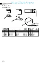
Page 107: ...HOLE OUTER HOLE D 1 0 C NO PARTS NO PARTS NAME DWG NO SIZE QTY D C H E10 1222764 Resin clamp NE41015 9 26 9 27 8 7 9 1 E11 0944528 Resin clamp NE41015 7 19 8 24 6 7 9 1 E14 0508162 Resin clamp NE4101...

Page 108: ...NO SIZE D C H E6 1656329 Tube clamp 4P159506 58 24 27 5 E16 1656343 Nylon coating tube clamp 4P159505 51 10 20 3 E29 1656398 Nylon coating tube clamp 4P159505 59 26 28 5 E22 1656381 Nylon coating tube...

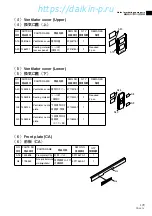
Page 109: ...acked to control box cover ass y F7 G3 2 G3 1 G20 A4 A5 A6 NO PARTS NO PARTS NAME REMARKS A6 1196113 Sealing material access panel DWG NO A5 1266207 Cushion material access panel 3P033608 1 3P001640 2...

Page 110: ...ant label 3P174603 1 A15 G4 NO PARTS NO PARTS NAME DWG NO A19 0981060 Ventilation cover 3P003175 1 1 A20 1266221 Sealing material access panel 4P016185 1 2 REMARKS Required 2 pcs NO PARTS NO PARTS NAM...

Page 111: ...SV Body B7 4 1411533 Reheat coil bypass solenoid valve body Coil B7 5 1266290 Reheat coil bypass solenoid valve coil 7 ESV Body B7 8 0088738 Economizer solenoid valve body Coil B7 9 1266290 Economizer...

Page 112: ...t you order the following best shrinkable tube together at the same time TR06 13 111 NO PARTS NO PARTS NAME REMARKS DWG NO HPT B16 1587959 High pressure transducer HPT 3P141602 1 LPT B15 1587942 Low p...

Page 113: ...air temp sensor 3PA61769 13 ST9503 13 Blue 6700 Indoor B B 4 DRS C27 1375341 Data recorder return air temp sensor 3PA61769 14 ST9503 14 Blue Red 6700 Indoor B B 5 EIS D4 156282J Evaporator inlet temp...

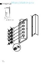
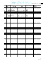
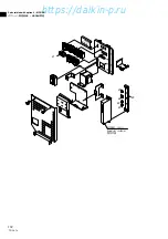
Page 114: ...ration See Service Manual for application NO PARTS NO PARTS NAME ILLUSTLATION 1270530 E m e r g e n c y magnet 1080263 Emergency coil cap DWG NO USE 3P017370 1 For electronic expansion valve 2P078385...

Page 115: ...Receptacle RS232C Female RS232C on the controller TYPE B B LXE10D LXE10D LXE10E LXE10E Receptacle Water proof type on the unit Parts No TR06 13 114 w 0 3m q 1 5m e r or t r 2 0m t 1 5m e q 1 5m NO PA...

Page 116: ...7 8 Frame Frame 1 2 3 4 5 6 7 8 RS232C Female RS232C Female 1 2 3 4 5 6 7 8 9 A B C Daikin made RS232C Female Red White Black Red White Black A B C D E 1 2 3 4 5 6 7 8 Daikin made RS232C Female Frame...

Page 117: ...6716 0420 Head Office Umeda Center Bldg 4 12 Nakazaki Nishi 2 chome Kita ku Osaka 530 8323 Japan Tel 06 6373 4338 Fax 03 6373 7297 Tokyo Office JR Shinagawa East Bldg 10F 18 1 Konan 2 chome Minato ku...

Reviews: