25
4-23
4.2.11 High-pressure switch (HPS)
●
Model ACB-KB15
●
Set point OFF : 2400kPa (24.47kg/cm
2
)
ON
: 1900kPa (19.37kg/cm
2
)
When the refrigeration pressure of the unit
rises abnormally, the compressor stops for
safety. The HPS will be activated when the
pressure exceeds the set point, as a result of
trouble with the condenser fan.
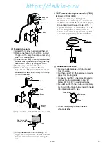
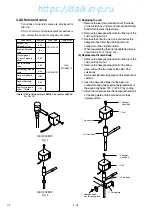
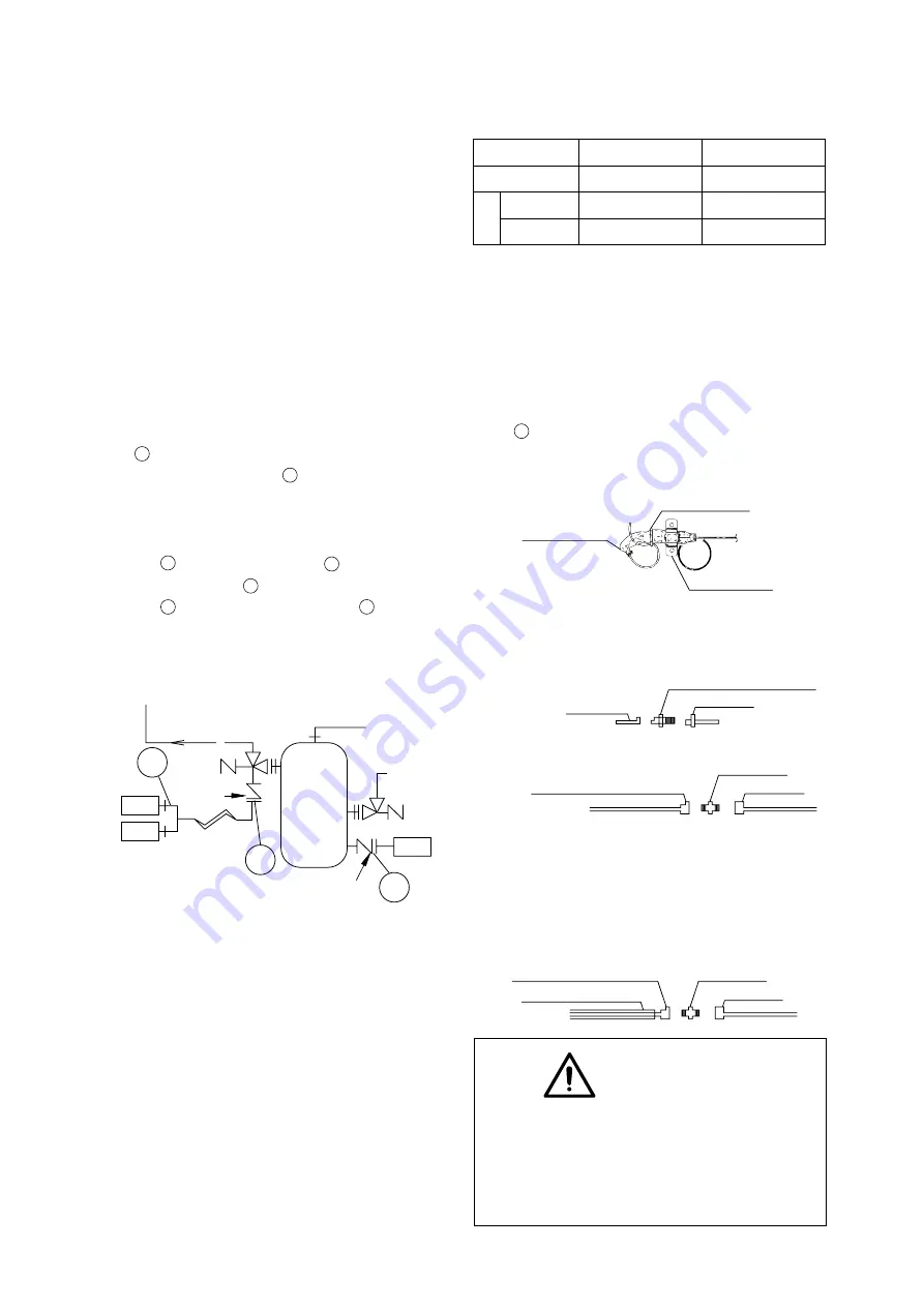
(1) Replacement procedure
q
Disconnect the lead wire from the control
box.
w
In order to prevent refrigerant from flowing
out, disconnect the high-pressure gauge
piping from the gauge joint (with check valve)
A on the compressor side.
e
Remove the flare nut B and mounting
screws of HPS on the casing at the left side
of the compressor.
r
Replace the HPS. After tightening the flare
nut B , tighten the flare nut A .
t
After tightening A , slightly loosen the flare
nut B , remove air, and retighten B .
y
After replacing carry out the refrigerant
leakage check, and make sure that there are
no leaks.
Disconnect
flare nut
here
Disconnect flare
nut here
B
A
C
COMPRESSOR
L P T
H P T
H P S
D
CAUTION
Do not expose the low pressure
transducer to hot air of a dryer for
excess time.
Otherwise, the transducer may be
damaged.
4.2.12 Low pressure transducer (LPT)
The LPT is located in the refrigerant circuit.
The operating low pressure value is displayed
on the controller indication panel.
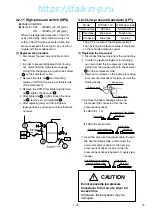
(1) Replacing the transducer
q
Disconnect the lead wire from the control box.
w
In order to prevent refrigerant from flowing
out, disconnect the low-pressure transducer
piping from the gauge joint (with check valve)
C on the compressor side.
e
Remove two screws on the clamp plate fixing
low pressure transducer in place, and cut the
binding bands.
t
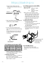
Insert the pressure transducer cable through
the heat shrinkage tube, and connect the
union joint and connector to the new low
pressure transducer. If paint on the low
pressure transducer is peeled off, apply clear
lacquer.
r
Remove the heat shrinkage tube, and
disconnect the connector from the low
pressure transducer.
¡
LXE10E-1, 1A
q
Clamp plate
w
Binding band
w
Binding band
Flare nut
Low pressure transducer
Connector
Flare nut
Union joint
Low pressure transducer
Heat shrinkage tube
Model
LXE10E-1,1A
LXE10E-1B and later
Transducer type
SPCL02
NSK-BC010F
Identification
color
Transducer
Blue seal
Black body
Connector
Blue tape
Nothing
¡
LXE10E-1B and later
Flare nut
Union joint
Low pressure transducer
001-030̲E-SM(LXE10E-1E)A4 2007.04.27 13:29 ページ 25
https://daikin-p.ru
Summary of Contents for LXE10E-1
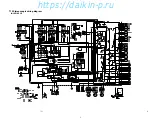
Page 32: ...31 7 10 7 14 Schematic wiring diagram LXE10E 1E https daikin p ru...
Page 33: ...32 https daikin p ru...
Page 34: ...33 7 11 7 15 Stereoscopic wiring diagram LXE10E 1E https daikin p ru...
Page 35: ...34 https daikin p ru...
Page 49: ...48 2 22 2 5 4 3 12 RSV CSV DEHUMID LED 1 30 RH 95 RH LXE10E 1 LXE10E 1A https daikin p ru...
Page 55: ...54 4 6 1 2 P 4 3 P 3 56 3 L LP HP LXE10E 1 LXE10E 1A LXE10E 1 LXE10E 1A https daikin p ru...
Page 58: ...57 4 18 2 120 248 F EV EV 4 2 5 TEV VTX 3410DMS 1 120 248 F https daikin p ru...
Page 66: ...65 LXE10E 1E 7 10 https daikin p ru...
Page 67: ...66 https daikin p ru...
Page 68: ...67 LXE10E 1E 7 11 https daikin p ru...
Page 69: ...68 https daikin p ru...
Page 105: ...Parts related with option 3 Indoor fanguard K1 TR06 13 104 https daikin p ru...

