7
CAUTION
Do not expose the low pressure
transducer to hot air of a dryer for
excess time.
Otherwise, the transducer may be damaged.
5.1 Low pressure transducer (LPT)
The LPT is located in the refrigerant circuit.
The operating low pressure value is displayed
on the controller indication panel.
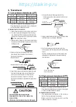
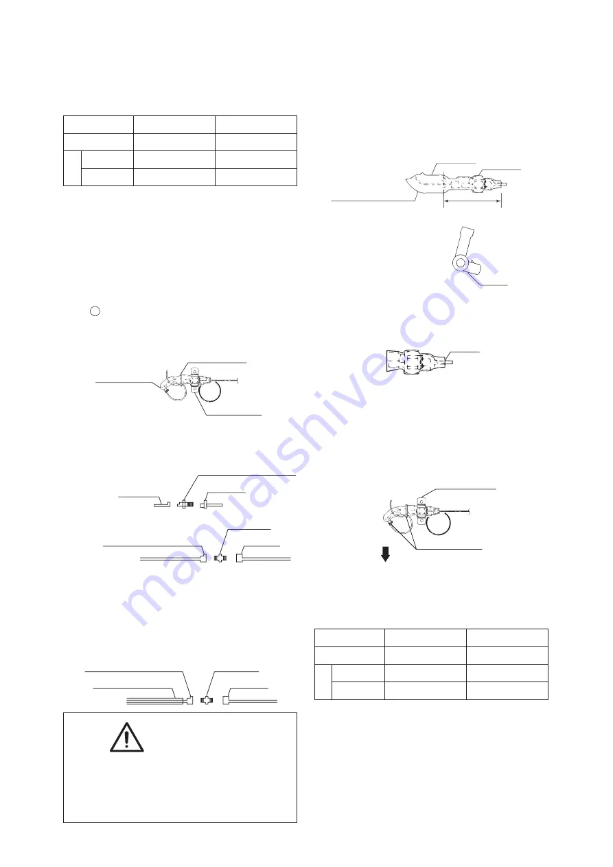
(1) Replacing the transducer
q
Disconnect the lead wire from the control box.
w
In order to prevent refrigerant from flowing
out, disconnect the low-pressure transducer
piping from the gauge joint (with check valve)
C on the compressor side.
e
Remove two screws on the clamp plate fixing
low pressure transducer in place, and cut the
binding bands.
t
Insert the pressure transducer cable through
the heat shrinkage tube, and connect the
union joint and connector to the new low
pressure transducer. If paint on the low
pressure transducer is peeled off, apply clear
lacquer.
r
Remove the heat shrinkage tube, and
disconnect the connector from the low
pressure transducer.
¡
LXE10E-A17
q
Clamp plate
w
Binding band
w
Binding band
Flare nut
Connector
Low pressure transducer
Flare nut
Union joint
Low pressure transducer
Heat shrinkage tube
Model
LXE10E-A17
LXE10E-A17A, A35, A35A
Transducer type
SPCL02
NSK-BC010F
Identification
color
Transducer
Blue seal
Black body
Connector
Blue tape
Nothing
¡
LXE10E-A17A, A35, A35A
Flare nut
Union joint
Low pressure transducer
5. Transducer
5.2 High pressure transducer (HPT)
The HPT is located in the refrigerant circuit.
The operating high pressure value is displayed
on the controller indication panel.
(1) Replacement procedure
The replacement procedure is the same as
that for the low pressure transducer.
Make sure that the fixing position and the
cable connection is correct.
y
Apply the heat shrinkage tube in the
following position, then shrink it with hot air
of a dryer.
u
Apply sealer between the heat shrinkage tube
and the flare nut. (Sealer :KE4898)
i
Fix the low pressure transducer with the
clamp plate, and fix the cable with the binding
band.
Fix the shrinkage tube end of the cable side
downward for prevention of water entering
into the tube.
r
Dryer
Make the heat shrinkage
tube fit in this area
Gauge
pipe side
Low pressure
transducer cable side
q
Heat shrinkage tube
w
Connector
e
Flare nut
q
Clamp plate
Fix the tube directing
the end downward
w
Binding band
Sealer
Model
LXE10E-A17
LXE10E-A17A, A35, A35A
Transducer type
SPCH01
NSK-BC030F
Identification
color
Transducer
Red seal
Red & Brown body
Connector
Red tape
Nothing
https://daikin-p.ru
Summary of Contents for LXE10E-A17
Page 9: ...8 https daikin p ru ...
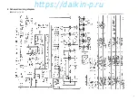
Page 10: ...9 6 Schematic wiring diagram LXE10E A17 A17A https daikin p ru ...
Page 11: ...10 LXE10E A35 https daikin p ru ...
Page 12: ... LXE10E A35A 11 https daikin p ru ...
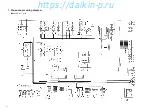
Page 13: ...12 7 Stereoscopic wiring diagram LXE10E A17 A17A https daikin p ru ...
Page 14: ... LXE10E A35 13 https daikin p ru ...
Page 15: ...14 LXE10E A35A https daikin p ru ...
Page 23: ...22 https daikin p ru ...
Page 24: ...23 6 シーケンス LXE10E A17 A17A https daikin p ru ...
Page 25: ...24 LXE10E A35 https daikin p ru ...
Page 26: ... LXE10E A35A 25 https daikin p ru ...
Page 27: ...26 7 実体配線図 LXE10E A17 A17A https daikin p ru ...
Page 28: ... LXE10E A35 27 https daikin p ru ...
Page 29: ...28 LXE10E A35A https daikin p ru ...
Page 81: ...MEMO https daikin p ru ...


