background image

19

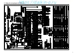
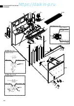
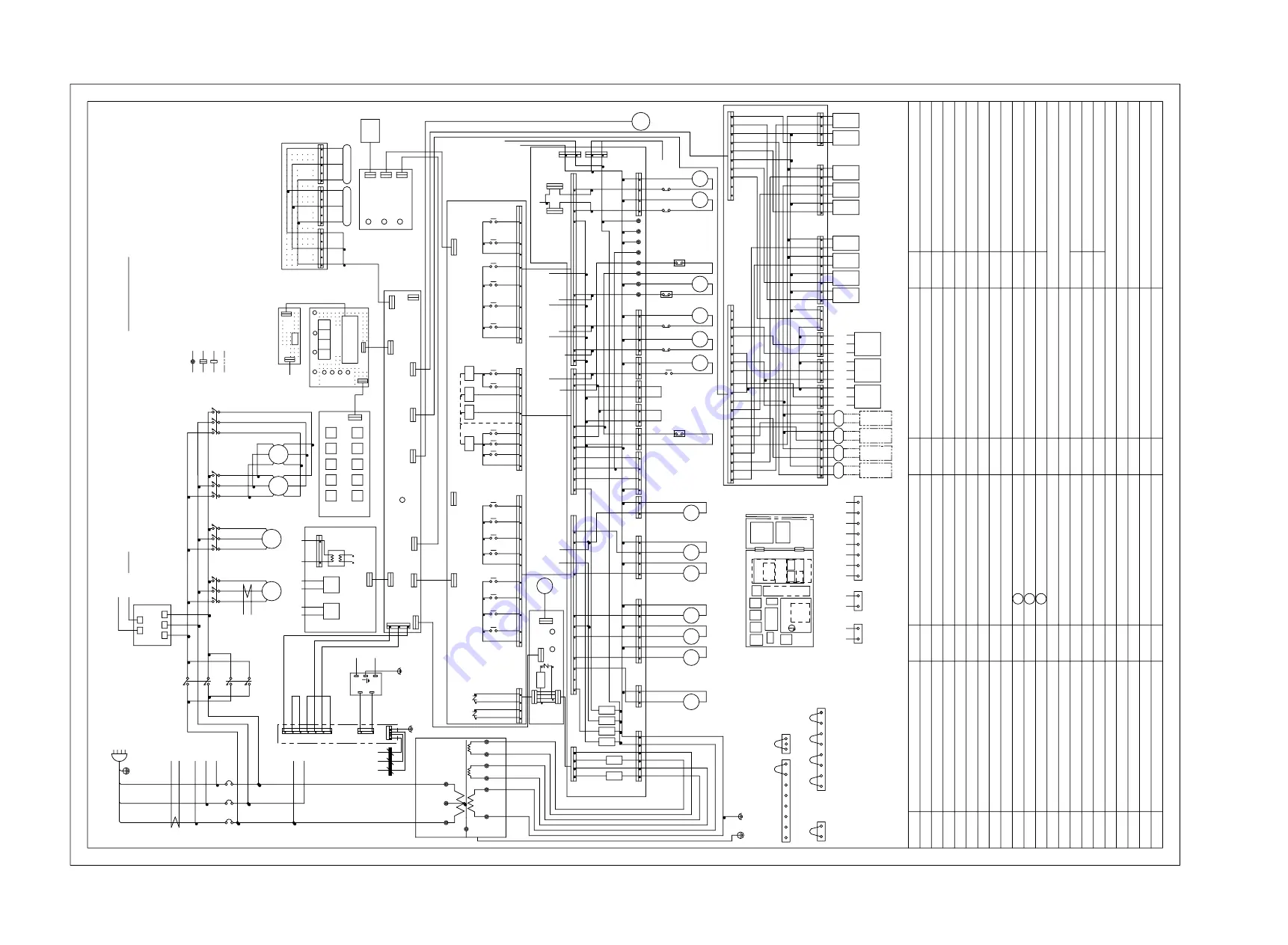
9.2 Schematic wiring diagram (LXE10E-A33A)

CONNECTOR

SCC1-1,-2

SHORT

CIRCUIT

SCC3

SCC2

SHORT

CIRCUIT

CONNECTOR

CONNECTOR

SHORT

CIRCUIT

EVAPORATOR

AMBS

4

APPLY

1

B

CN32

C

C

1

A

1

PPR1

TB1

3

3

5

3

5

5

A

PPR2

CN30

CN31

B

7

AIR

REMOTE

RPP

PRESSURE

32

BREAKER(30A)

LCD

CN31

LD5

LD6

LD

9

-12

LD2 LD1

LD3

LD7

EC3

LD4

LD

8

EC4

301

REMOTE

2

VALVE

TRANSFORMER

BLK

U

U2

BLK

43

YLW

33

CM

BLU

3

9

WHT

CFM

W

V1

WHT

EFM2

V2

W2

BRN

U1

44

U1

40

V1

V2

42

W2

34

3

V

CT2

22

WHT

RED

BLK

U

CC

W

23

4

24

EFM1

W1

U2

RED

35

V

RED

W1

EFH

CFC

EFL

41

EVAPORATOR

FAN

T

4

5

*5

3

11

20

4

*

8

1

LEDA

3

3

Fu1

(GRN)

KEY

13

2

1

CPU

BAT

CN26

TEST

8

12

3

BOARD

DEVICE.

INDICATOR(EC7)

SUCTION

INJECTION

3

BLK

TB1

FUSE

G

3

CN7

EC5

DCHS

3

CN2

SS

2

RED

RSV

*13

CN37

CTP

5

1

CN25

CN10

SWITCH(BATTERY

UR3

SENSOR

2

3

LXE10E-A33

DIODE(SUPPLY)

EC3

HPT

17

5

12

5

(DECOS)

4

NORMAL

RETURN

460V

THE

9

CN21

BOARD

1

Fu1

RS

VALVE

PHC

3

CN24

CN22

EFL

BSV

(BLU)

(250V,10A)(TB1)

線番号100以降

3

RY

RY

PRINTED

SUPPLY

1

1

6

1

HSV

4

LD3

LPT

2

4

2

PCC1

*7

INDICATOR)

5

8

CN22

4

REVERSE

0V

HPT

CONTACTOR

TrC

1

8

7

8

SENSOR

BLK

WIRE

3

153

1

RED

BS7

PHC

1

W1

RCD

3

RPP

1

1

5

BLK

および、リモー

CN27

CM

CARGO

BOARD

6

8

LIGHT-EMITTING

1

PRESSURE

1

9

CN14

AMBS

1

REHEAT

5

DISPLAY

CONDENSER

CORE

202

4

166

165

5

10

9

164

8

16

8

16

9

1

RCD(YORK)

7

2

1

6

BLU

3

13

3

167

7

5

WHT

170

PCC1

HPS

6

6

CFC

PROTECTOR

FAN

2

RECEPTACLE

3

EXPANSION

10

1.DO

2

CN2

THE

4

RECORDER

AFTER)AND

LD4

1

60HZ

1

BS

8

11

CN1

CN

8

4

EFL

151

EFH

8

LSV

MONITOR-GREEN(EC1)

EC7

CURRENT

  を行わぬこと。

5

1

3

6

4

8

2

7

10

EC1

SPEED

SENSOR

1

EFM1,2

3

RY

U2

5

8

2

COMPRESSOR

BLK

1

SOLENOID

BOX

3

(DECOS)

CONTACTOR

CN12

REFRIGERATION

SOLENOID

8

6

EC4

SPEED

RY

2

PCC2

6

6

CRYSTAL

PROTECTOR

DEFROST

INLET

8

INSULATION

INDICATOR(EC7)

137

RY

13V

SENSOR

COMMUNICATION

8

TEMP.SENSOR

TRANSDUCER

4

2

6

2

COMPRESSOR

CT1,2

COMMUNICATION

4

SW1

0V

9

2

4

1

CB

24V

OF

CONTACTOR

4

LD1

LIGHT-EMITTING

U1

4

CN11

3

BLK

2

COUPLER

SENSOR

PCC1,2

131

4

DIODE(ALARM)

LED1

3

HUMIDITY

(BLK)

WIRING

BS2

31

1

LIGHT-EMITTING

9

(BRN)

CN3

8

EV

155

CN17

RY

BOARD

Fu4

E

104

VALVE

CN16

155

ON

*5

4

ADAPTER

1

RY

(BLU,RED)

U3

CN1

9

MODULATING

5

SOLENOID

SMV

SGS

1

16

B

1.操作回路

RCD

1

12

*6

CN10

4

TB1

1

8

7

2

4

WHT

CN1

USDA1-3

LED1

2

(COOL)

1

101

50HZ

1

LD

8

LEVEL

1

7

EC

8

CAUTION

5

BLK

ISV

13

9

OPTIONAL

133

S

2

DCHS

RY

COMPRESSOR

2

16

CN

8

1

DIODE

CC

POSITION

AIR

10

CIRCUIT(ON

CN4

2

CN33

1

Fu6

5

2

MTP

*5

9

13

8

2

2

BS1-10

15

DSV

)

6

RED

1

DSS

CIRCUIT

BOARD

BS5

CN1

8

3

106

LOW

135

W3

CN5

CTS

2

USDA3

RSV

RED

CN6

Fu2

FERRITE

1

400V

PHC

14

3

CN2

PCC1,2

RS

USDA2

2

PHASE

146

*2

TeS1

LSV

(BRN)

ELECTRONIC

EOS

CN12

CTR

101

5

SCC1,2,3:BEHIND

DATA

No.100

4

POWER

136

415V

6

5

9

B

1

3

SCC1-1(BLU)

SERVICE

FILTER

3

LED2

202

12

  トコミニュケーションデバイスには絶縁試験

*2

EV

LOW

TEMP.

(PT,CT)

SERVICE

CN20

RY

CN2

9

DIODE(COMP)

TRANSDUCER

2

CFC

7

6

5

COIL

RY

BLK

BOARD

FAN

1

CONTAINER

GAS

DRS

7

15

2

LD-A

HIGH

HSV

EC7

*3

143

CONTACTOR

7

LIQUID

COMPRESSOR

BATTERY

VALVE

EC7

NOT

B

12

LED2

CONTROLLER

CN-C1

RETURN

PHC

THE

PCC2

EC

8

SCC2(BLU)

AMBIENT

HIGH

RY

CIRCUIT

13

9

6

CT2

1

CTR

(BLK)

BOARD(DECOS)

CN

8

2

DRS

14

0

POTENTIAL

TRANSFORMER

R

11

CB

WIRING

EVAPORATOR

EFH

TEMP.

3

CN

40

Z1

C

UR1

1

440V

2

P

PHOTO

DISCHARGE

EFL

HuS

RANGE)

VALVE

LIGHT-EMITTING

BLK

LED1

171

*4

UNIT

VALVE

BLK

G

4

EFH

EVAPORATOR

A5V

CN

36

DSV

LD6

USDA1

9

CN

8

3

DISPLAY

24V

SOLENOID

SENSOR

2

TrC

SGS

CTS

10

TERMINAL

1

BATTERY

RY

WHT

CN11

1

152

MOTOR

10

DEVICE(YORK)

2

104

8

1

EFL

Fu6

PT

SCC1,2,3

4

DIODE(DE-HUMID)

2

BLK

2

CN

9

3

5

LD2

EC6

3

CT1

4

BLK

10

DIAGRAM

1

9

CN20

302

MTP

*

8

415V

*10

2

(COOL):BLU,(HEAT):RED

13

LIGHT-EMITTING

6

T2

Z1C

RECEPTACLE

(HEAT)

8

HIGH

1

3

4

10

VALVE

ISV

DSS

SUCTION

(

SCC1-2(RED)

9

LIGHT-EMITTING

301

POWER

P

105

SENSOR

CN16

1

SOLENOID

CN

8

*

9

1

CTP

MOTOR

8

8

CN1

9

EC2

SPECIFICATION

LD7

1

ESV

CB

CN24

BS1

2

Fu3

*3

SWITCH

FUSE

2

UR1-3

NOISE

SENSOR

2

BLK

14

NF

CFC

NF

PCC

SUPPLY

SW1

PHC

1

CN1

8

(GRN,RED)

11

3

CN3

5

13

1

EC5

WHT

2

5

U1

WHT

4

PC.PORT

BAT

SENSOR

CN23

8

PLUG

CN1

13

EC

8

Fu6

CN2

6

(250V,5A)(EC6)

LIGHT

PHASE

9

BLK

6

RPP

CN-C2

MONITOR-GREEN(EC6)

DIODE

OUTLET

132

CN14

(WHT)

SENSOR

5

145

RY

LIGHT-EMITTING

RY

CONTROL

12

LCD

R

BYPASS

ECONOMIZER

CN3

9

EIS

CN15

134

EMERGENCY

11

BSV

(DECOS)

THERMAL

(250V,1A)(EC

8

)

BATTERY

1

LPT

LD-A

144

6

注意

PT

BS

9

CONTACTOR

3

SCC3(WHT)

1

PCC

2

1

Z1C

PARTS

AT

SCREW

TERMINAL

TAPE

FOR

NOTES

MEANS COLOR

SENSOR.

TAB

2.(

DISTINGUISHING

END

TERMINAL

OPTIONAL

)

1.

CONNECTOR

RECEPTACLE

DATA

EC2

*

9

PUSH

BOARD

3

1

3

CN13

11

2

VALVE

Fu1-6

133

7

4

USDA

RPP

CONTROL

Fu1

G

EIS

LIGHT-EMITTING

2

TB1

TB1

4

SUPPLY

LIGHT-EMITTING

FAN

LIQUID

SWITCH

2D0567

9

1-1

MOTOR

CONDENSER

7

CN17

SS

LEDA

4

0V

5

RY

RY

PRESSURE

BS3

G

6

3

8

0V

GAS

13

HOT

DIODE(R.H.)

RELAY

*4

Ry1-1

9

CN13

G

VALVE

7

RY

CFM

PROTECTOR

7

LED1

W2

3

RY

CC

6

USDA

3

6

BACK

10

3

12

201

EC4

SOLENOID

(YLW)

LIGHT-EMITTING

*7

SMV

BAT

7

AIR

*1

7

6

EC1

Fu5

302

W

HPS

G

EC5

BS6

SHEET

FUSE

EFH

CN6

4

13

POWER

CORRECTION

UR2

*6

10

CARGO

(EC6)

SENSOR

17

CN34

I/O

DIODE(IN

EOS

2

10

8

SOLENOID

EC3

BLK

ESV

BS4

EC1

S

1

EC6

*13

201

140

RECORDER

3

EVAPORATOR

BUTTON

(DECOS)

COND.

LD

9

-12

PPR1,2

154

1

TrC

TRANSFORMER

5

CN3

DIODE(DEFROST)

CT1

RY

AIR

DIODE(RETURN)

MOTOR

LD5

2

THERMAL

FAN

HuS

EC6

2

EC2

AND

NF

BS10

U2

GAS

CN23

*10

3

2

2

3

*1

CN32

CC

5

CN21

4

17-20̲LXE10E-A33̲A3.indd   19

17-20̲LXE10E-A33̲A3.indd   19

07.2.28   6:48:51 PM

07.2.28   6:48:51 PM

https://daikin-p.ru

Summary of Contents for LXE10E-A33

Page 1: ...TR06 04A Marine type Container Refrigeration Unit Service Manual Parts List Optional Functions LXE10E A33 LXE10E A33A https daikin p ru...

Page 2: ...those of the service manual TR01 09A For the marked items refer to the details in the following pages NO Item Different points from service manual Maintenance and Repair 1 Dehumidification function R...

Page 3: ...nsducer characteristics table 7 4 7 8 Low pressure transducer characteristics table 7 4 7 9 Piping diagram 7 5 7 10 Pilot lamps and monitoring circuit 7 6 7 11 Fuse protection table 7 7 7 12 Schematic...

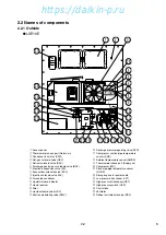
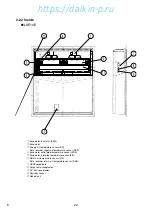
Page 4: ...be within 10 2G Item 1 12 13 6 10 4 11 5 9 8 2 3 7 q Compressor w Air cooled condenser e Receiver r Evaporator t Control box Outside switch manual defrost switch Inside circuit breaker y Condenser fa...

Page 5: ...sting system Dual timer on demand defrost and manual switch Detecting the temperature of evaporator outlet pipe and return air Electronic expansion valve Capacity control Capacity control with hot gas...

Page 6: ...2 Liquid receiver 3 Drier 4 Liquid solenoid valve LSV 5 Suction modulating valve SMV 6 Discharge pressure regulating valve DPR 7 Compressor suction pipe temperature sensor SGS 8 Ambient temperature se...

Page 7: ...ture sensor DSS r Evaporator outlet pipe temperature sensor EOS t Evaporator inlet pipe temperature sensor EIS y Return air temperature sensor RS Data recorder return air temperature sensor DRS u USDA...

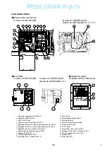
Page 8: ...oard 8 Transformer TrC control circuit 9 Magnetic contactor for compressor CC 0 P C B for humidity sensor HUS 1 Modem RCD 2 Noise filter NF GOperation panel Outside of the control box GController In c...

Page 9: ...F set point Reset After 3 minutes elapsed Overcurrent protection set point Cutout OFF 26 0A PT CT board CT2 Reset After 3 minutes elapsed Current control Control 50Hz 16 1A PT CT board CT1 60Hz 17 4A...

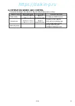
Page 10: ...peration description Frozen mode 10 1 C to 30 0 C Return air Compressor ON OFF control 13 82 F to 22 0 F temperature sensor 30 0 C to 10 0 C Supply air Capacity control operation Chilled mode 86 0 F t...

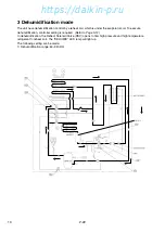
Page 11: ...ecute dehumidification controller setting is required Refer to Page 3 12 In dehumidification the Reheat Solenoid Valve RSV opens to flow high pressure and high temperature refrigerant to reheat coil T...

Page 12: ...11 KVA 2 Automatic pump down Pump down can be executed automatically Refer to Automatic pump down in 4 1 3 TR01 09A 3 Dehumidification mode setting Dehumidification mode can be executed in this mode...

Page 13: ...lay E315 PT CT board failure Restart after 3 minutes E401 Supply air temperature sensor SS malfunction Back up operation E402 Data recorder supply air temperature sensor DSS malfunction Back up operat...

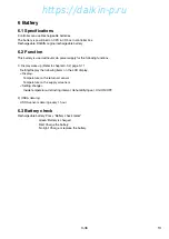
Page 14: ...y wake up Refer to chapter 3 3 2 page 3 11 Setting Display the following items on the LCD display Display Temperature on the return air sensor Temperature on the supply air sensor Setting change Insid...

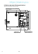
Page 15: ...ry Detach the cover of battery and replace the battery 3 40 Voltage indicator Battery check meter Rechargeable battery In case of LXE10E A33A Battery fixing plate Rechargeable battery In case of LXE10...

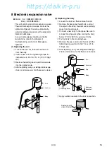
Page 16: ...o the original state r After replacing carry out refrigerant leakage check and make sure that there are no leaks e Body q Coil w Lock nut 2 Replacing the body q Loosen the lock nut then remove the coi...

Page 17: ...RVICE PORT LOW QUICK JOINT TYPE CHECK VALVE RECEIVER RSV HSV DSV DPR BSV ISV LSV ESV HEAT EXCHANGER EV Electronic Expansion Valve SMV Suction Modulation Valve DPR Discharge pressure regulator LSV Liqu...

Page 18: ...17 9 2 Schematic wiring diagram LXE10E A33 https daikin p ru...

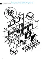
Page 19: ...18 9 3 Stereoscopic wiring diagram LXE10E A33 BLK BLU GRN GRY RED WHT BRN YLW https daikin p ru...

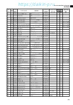
Page 20: ...D CN6 Fu2 FERRITE 1 400V PHC 14 3 CN2 PCC1 2 RS USDA2 2 PHASE 146 2 TeS1 LSV BRN ELECTRONIC EOS CN12 CTR 101 5 SCC1 2 3 BEHIND DATA N o 1 0 0 4 POWER 136 415V 6 5 9 B 1 3 SCC1 1 BLU SERVICE FILTER 3 L...

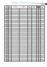
Page 21: ...C N 3 9 4 T B 1 CT C 4 3 T B 1 C N 4 T B 1 C N 3 8 3 B L K 1 4 0 C W H T 0 V C N 1 1 T B 1 C N 3 9 2 1 3 9 1 3 V A B L U 3 C N 3 2 PT E F L B C N 8 1 3 7 B L K 6 U 2 1 0 WHT C N 2 2 4 1 C N 2 4 3 3 1...

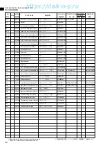
Page 22: ...as a set so please contact with the nearest DAIKIN PARTS CENTRE 3 Index symbols Meaning of the ranking A B and C are as follows A The most important spare parts 1 The parts whose malfunction cause fa...

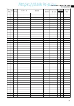
Page 23: ...POWER 5 5 10 10 CONDENSER COOLING TYPE NIL AIR and WATER COOLED TYPE A AIR COOLED TYPE OPTION NUMBER L X E E 5 5 10 10 A Note R GIVEN AFTER OPTION NUMBER STANDS FOR REVISION AND IT IS GIVEN FOR THE U...

Page 24: ...arts related with option 2 MODEM 57 K Parts related with option 3 Others 58 L List of size for standard pipe clamp 60 1 Resin clamp 2 Tube clamp 3 Cushion rubber for pipe clamp M Notes for ordering sp...

Page 25: ...24 A30 A18 A7 A13 A29 A35 A31 A32 A33 A36 A34 A17 A20 A9 A8 E13 A19 A1 A35 A31 A32 A33 A34 A14 A16 A2 A3 A15 Refer to 63Page E55 A11 A10 A12 A5 A6 A4 Refer to 62Page A19 Refer to 63Page A26 A28 A21 A2...

Page 26: ...1 Refer to Page63 A18 1661321 Fixing plate 3P170535 1 A24 0275145 Plain washer Woods round type 4SK07006 6 M6 A25 1266214 Holding plate ventilator 4P067052 1 A29 1496820 Protection cover 2 4P085921 2...

Page 27: ...UNIT REMARKS A36 1787456 Front panel right RESIN 2P175878 1 E13 1266788 Resin clamp NE41015 12 MILK WHITE E55 1267077 Packing for prevention of vibration 4P050050 1 1 6 6 2 2 LXE10E A33 A33A A35 1267...

Page 28: ...Parts related with the unit outside 27 NO INDEX PARTS NO PARTS NAME DWG NO TYPE SPECIFICATION QTY UNIT REMARKS LXE10E A33 A33A https daikin p ru...

Page 29: ...g pipe Feeler bulb LSV SMV DPR B2 B8 1 1 B8 1 2 B8 1 3 B8 1 5 B8 1 4 B3 2 2 B3 2 B3 2 1 B3 2 3 B19 B16 B11 B15 B3 6 B3 5 B24 B14 B1 B25 B9 2 B9 B3 3 B13 B3 B6 B8 B21 B5 B8 1 B3 4 B4 4 B4 B9 1 2 B9 1 1...

Page 30: ...noid valve coil 3P010453 1 Refer to Page64 B7a Expansion valve pipe ass y 2P163079 1 B7a Expansion valve pipe ass y 2P163079 3 B7 1 C 1505748 Filter 3P011071 1 B7b ISV ESV pipe ass y 3P163059 1 B7 5 A...

Page 31: ...J Service valve cap 3P048907 1 KU B9 2 1266315 Square flange 4PA61542 1 B10 A 1241385 Drier ass y 3P069859 1 B11 A 098332J Sensor discharge pipe temperature DCHS 3SA48009 10 Refer to Page66 B12 A 0798...

Page 32: ...Parts related with refrigerant piping outside 31 NO INDEX PARTS NO PARTS NAME DWG NO TYPE SPECIFICATION QTY UNIT REMARKS LXE10E A33 A33A https daikin p ru...

Page 33: ...KE44RTV b 1 C32 A E57 C15 C1b C8 C1a C2 Option C13 C12 C11 Option C13 C18 C4 C3 C6 C6 C19 C19 C5 C23 C14 C16 C21 C22 C9 A Detail of A C23 Detail of C23 C25 DSS Green Red C24 SS Green Without recorder...

Page 34: ...135125 Hinge 3P043374 1 C22 1266524 Support plate 4P061342 1 C23 1605466 Mounting plate 4P144433 1 C26 A 1713354 Sensor RS 3PA61769 18 Refer to Page66 C12 1634196 Fan guide ass y 3P153482 1 C13 166717...

Page 35: ...1326844 Fixture 4P089944 1 C38 1683910 Rear plate Upper fixture 4P175469 1 C39 1685170 Pan head screw 4P167690 1 C40 1685187 Washer 4P170127 5 C41 840001 Drop out prevention washer R4718607 5 C41 8400...

Page 36: ...Parts related with the unit inside 35 NO INDEX PARTS NO PARTS NAME DWG NO TYPE SPECIFICATION QTY UNIT REMARKS LXE10E A33 A33A https daikin p ru...

Page 37: ...erant piping inside 36 D4 Detail of D4 D5 Detail of D5 E60 D7 D4 Feeler bulb Feeler bulb inserting pipe 45 45 E63 D5 E30 Feeler bulb D3 1 D3 10 D3 6 D3 2 D3 2 D6 D3 4 D3 3 D3 7 D2 D1 D4 D5 D3 5 D3 D3...

Page 38: ...Insulation tube liquid pipe 1 3P167441 1 D3 5 1380918 Thermal insulation tube 4P103439 1 D3 6 1380925 Thermal insulation tube 4P103439 2 D3 7 1380932 Thermal insulation tube 4P103439 3 D3 8 1380949 T...

Page 39: ...Other parts Pipe clamp sealing and insulation material etc 38 E Section of E B Detail of B Tie wrap Wires E73 C Detail of C E91 E11 E13 B E E C E83 E82 E79 E83 Condenser coil https daikin p ru...

Page 40: ...5 L XX mm indicates the length of cushion rubber E35 Cut to suit pipe size A B View A B E29 E90 E90 E90 E21 L 60mm E89 E1b E16 D View D Receive part detail Dryer part detail Pressure tranducer detail...

Page 41: ...Other parts Pipe clamp sealing and insulation material etc 40 EOS E11 E12 A E23 E52 E60 E79 EFM1 EFM2 E79 A VIEW A E15 E15 https daikin p ru...

Page 42: ...Other parts Pipe clamp sealing and insulation material etc 41 FAN GUIDE E43 E44 E45 E37 E46 E46 E38 E37 E41 E54 E42 E36 E39 E39 https daikin p ru...

Page 43: ...Other parts Pipe clamp sealing and insulation material etc 42 E69 E70 E71 E63 E76 E64 E66 E65 E77 E61 https daikin p ru...

Page 44: ...5817 2 Page39 E35 1584253 Cushion rubber NE41013 3 300 E36 1386947 Sealing material evaporator frame 4P090149 1 Page41 E43 1381043 Sealing materialL patch plate3 4P095038 1 Page41 E45 1267008 Sealing...

Page 45: ...l insulation tube 4P081186 1 Page42 E70 1267262 Thermal insulation tube 4P081187 1 Page42 E71 1448371 Suction solenoid valve insulator 2P079441 1 Page42 E73 1267293 Thermal insulation tube 4P011309 4...

Page 46: ...Other parts Pipe clamp sealing and insulation material etc 45 NO INDEX PARTS NO PARTS NAME DWG NO TYPE SPECIFICATION QTY UNIT REMARKS LXE10E A33 A33A https daikin p ru...

Page 47: ...Control box 46 F7 1 F7 2 F7 9 F13 F7 3 F16 1 F16 2 F7 8 F7 4 F7 7 F61 F7 5 F7 6 F4 F18 F30 F27 F59 F23 F24 F22 F58 F17 F33 F46 F25 F26 F28 F29 F68 F57 F50 F39 F7 LXE10E A33 https daikin p ru...

Page 48: ...4 8 F34 4 F34 F34 8 1 F34 11 F34 15 F34 5 F78 F76 F79 F77 F34 6 F34 1 F34 12 F34 13 F34 14 F34 10 F44 F31 1 F45 F31 F38 F37 F35 F40 F49 F36 F36 F39 F34 9 F64 F63 F66 F48 F65 F67 F20 F6 F19 F34 7 F62 F...

Page 49: ...Control box 48 F7 1 1 F7 1 2 F7 9 F7 3 F16 1 F75 F16 2 F7 8 F7 4 F7 7 F7 1 3 F61 F7 5 F7 6 F7 2 F18 F30 F27 F23 F73 F24 F22 F58 F17 F25 F59 F33 F46 F76 F57 F39 F7 LXE10E A33A https daikin p ru...

Page 50: ...4 7 F20 F34 F34 3 F34 2 F34 4 F28 F6 F3 F42 F72 F74 F48 F36 F64 F63 F67 F34 8 1 F34 8 F34 5 F13 F34 6 F34 12 F34 13 F34 14 F34 10 F31 1 F34 9 F31 F38 F37 F35 F40 F49 F50 F39 F41 F3 F26 F28 F69 LXE10E...

Page 51: ...3P030317 1 F17 1387197 Set plate 1 2P095432 1 F25 C 1562796 Low frequency transformer 3P139293 1 F26 C 0991531 PC port connector 3P010803 1 F26 C 1381113 PC port connector 3P073218 1 F13 1136539 Clam...

Page 52: ...14 840002 Drop out prevention washer R4718607 6 F41 1743216 Wire ground flexible tube 4P010926 7 F42 833302 Nylon nut R4716460 1 M4 F44 1099940 Support bushing PCB MI49531 11 F34 11 1136539 Clamp 4P01...

Page 53: ...ensor HUS 3PA61738 3 RHU 600A D2 F73 1684425 Mounting plate battery 4P170758 1 F73 A 0954640 Noise filter 2PA51273 1 ZAC2206 11 F74 1684432 Cushion rubber 4P171494 1 F74 1780291 Protection plate 4P176...

Page 54: ...Control box 53 NO INDEX PARTS NO PARTS NAME DWG NO TYPE SPECIFICATION QTY UNIT REMARKS LXE10E A33 A33A 46 59 LXE10E A33 TR06 04A 2007 03 06 14 34 53 https daikin p ru...

Page 55: ...tion A Detail location of nameplate solenoid valve Name plate solenoid valve G9 5 G1 G2 G10 G3 G19 G12 G4 G5 G6 G11 G18 G20 G9 G8 Inside of Control Box G16 G7 G14 G17 G13 G15 46 59 LXE10E A33 TR06 04A...

Page 56: ...381346 Name plate check point supply 4P103582 1 G9 1605491 Name plate solenoid valve location 4P151256 1 G9 1739419 Name plate solenoid valve location 4P182831 1 G10 1495214 Caution label reheat coil...

Page 57: ...ceptacle 2P146266 1 I3 C 0991531 PC port connector 3P010803 1 I4 1267541 Cover ass y PC port 3P010743 1 I5 C 1381113 PC port connector 3P073218 1 I8 1381221 Straight pin 3P040139 1 I9 1622597 USDA Rec...

Page 58: ...4640 Noise filter 2PA51273 1 ZAC2206 11 J2 1448410 Mounting plate modem 4P081133 1 J3 1267736 Connector for MODEM 3P012038 3 BLA3 J4 1267743 Connector for MODEM 3P010371 7 J7 1780291 Protection plate...

Page 59: ...Parts related with option 3 Others 58 K2 K5 K3 K4 K1 Indoor fan guard Evaporator coil K6 https daikin p ru...

Page 60: ...nside fan cover 3P150480 1 K2 1605484 Fixture 4P150653 1 K3 1605307 Inside fan cover stay 3P150525 1 K4 1381500 Fixture 3P098695 1 K5 1381517 Fixture 3P098695 2 K6 1683927 Evaporator ass y 2P163797 1...

Page 61: ...OLE INNER HOLE OUTER HOLE D 1 0 C NO PARTS NO PARTS NAME DWG NO SIZE QTY D C H E11 0944528 Resin clamp NE41015 7 19 8 24 6 7 9 2 E10 1222764 Resin clamp NE41015 9 26 9 27 8 7 9 1 E12 0142492 Resin cla...

Page 62: ...clamp 4P143802 51 10 20 3 6 E17 1584208 Nylon coating tube clamp 4P143802 52 12 21 3 1 E21 0016290 Tube clamp NE31016 56 20 25 5 1 E22 1584239 Nylon coating tube holder 4P143802 71 6 4 20 1 4 E27 126...

Page 63: ...E REMARKS A4 1612576 Access panel FRP Without cushion and sealing material A6 1196113 Sealing material access panel F7 4 G3 G12 F7 7 DWG NO 1P006678 5 A5 1266207 Cushion material access panel 3P033608...

Page 64: ...terial Ventilator 4P016185 1 NO PARTS NO PARTS NAME DWG NO A15 1661299 Front plate CA 2P165976 1 G18 1178843 Name plate refrigerant 3P009750 1 G4 1306530 Brand name label 4P085985 1 A19 A20 A15 G4 G18...

Page 65: ...l 4 BSV Body B7 4 1411533 Gas bypass solenoid valve body Coil B7 5 1266290 Gas bypass solenoid valve coil 5 ESV Body B7 6 0088738 Economizer solenold valve body Coil B7 5 1266290 Economizer solenold v...

Page 66: ...recommend that you order the following best shrinkable tube together at the same time NO PARTS NO PARTS NAME REMARKS E84 1605509 Heat shrinkable tube Must be applied when replacing above sensors DWG...

Page 67: ...2118 2 ST9703 2 Brown 2500 Indoor EVP 6 EOS D5 156283J Evaporator outlet temp sensor 3PA61769 15 ST9503 15 Yellow 2600 Indoor EVP 7 DCHS B11 098332J Discharge pipe temp sensor 3SA48009 10 ST9701 10 28...

Page 68: ...n See Service Manual for application NO PARTS NO PARTS NAME ILLUSTLATION 1270530 E m e r g e n c y magnet 1080263 Emergency coil cap DWG NO USE 3P017370 1 For electronic expansion valve 2P078385 2 Suc...

Page 69: ...MOL MOL LXE10D Receptacle RS232C Female RS232C on the controller TYPE B B LXE10D LXE10D LXE10E LXE10E Receptacle Water proof type on the unit Parts No w 0 3m q 1 5m e r or t r 2 0m t 1 5m e q 1 5m NO...

Page 70: ...Frame Frame 1 2 3 4 5 6 7 8 RS232C Female RS232C Female 1 2 3 4 5 6 7 8 9 A B C Daikin made RS232C Female Red White Black Red White Black A B C D E 1 2 3 4 5 6 7 8 Daikin made RS232C Female Frame 4 Re...

Page 71: ...MEMO https daikin p ru...

Page 72: ...Center Bldg 4 12 Nakazaki Nishi 2 chome Kita ku Osaka 530 8323 Japan Tel 06 6373 4338 Fax 06 6373 7297 Tokyo Office JR Shinagawa East Bldg 10F 18 1 Konan 2 chome Minato ku Tokyo 108 0075 Japan Tel 03...

Reviews: