3-35
3.6 Controller replacement and software upgrade
3.6.1 Controller replacement
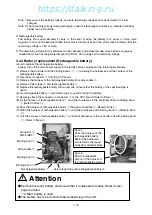
<Replacement procedure for the controller>
¡
Always turn off the main power supply to the facility before carrying out the following procedures.
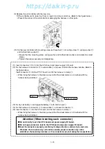
(1) Remove binding band
q
fixing each harness to the controller unit.
Remove binding band
w
binding harnesses.
→
Take care not to damage the harnesses.
(2) Disconnect round solderless terminal
e
from the power supply I/O board.
Disconnect the harness of terminal No.139 from wire saddles
r
and
t
.
(3) Disconnect connector
y
from the CPU board and the harness from clamp
u
, respectively.
(4) Disconnect connector
i
from the CPU board and the harness from wire saddle
r
, respectively.
(5) Remove the Velcro tape
!0
and remove dry cell battery or rechargeable battery
!1
.
→
Properly store the removed battery for reuse.
(6) Disconnect connector
!2
of the PT/CT board and the harness from clamp
!3
, respectively.
Pull out connector
!2
from the inner side of the harness, and disconnect the harness from wire
saddle
r
.
(7) Disconnect connectors
!4
to
!6
from the CPU board and power supply I/O board.
→
It is not necessary to disconnect the short-circuit connector or empty connector.
(8) Remove mounting screw (with washer)
!7
, mounting screw
!8
, spring washer
!9
and toothed lock
washer
@0
of the controller.
→
Properly store the removed screws and washers for reuse.
Mounting screw
!7
(with washer)
×
4 pieces
Mounting screw
!8
×
1 piece
Spring washer
!9
×
1 piece
Toothed lock washer
@0
×
1 piece
Clamp
!3
Harness bundle
(Refer to the figure below.)
Wire saddle
t
Wire saddle
r
Binding band
w
×
2 pieces
Connector
i
(CPU board)
CN48 (BATTERY)
Connector
!2
(PT/CT board)
CN2 (EC5)
Connector
!6
(Power supply I/O board)
CN4 (optional :MODEM)
Velcro tape
!0
Dry cell battery or
rechargeable battery
!1
Round solderless terminal
e
(Power supply I/O board)
103 (optional, T/F A2 cable)
108 (optional, T/F A2 cable)
123 (optional, T/F A2 cable)
125 (optional, T/F A2 cable)
131 (CTP)
132 (CTP)
139 (MTP)
140 (CFC)
Connector
!4
(CPU board)
CN42 (optional :FAS)
CN43 (thermistor)
CN44 (LPT, HPT)
CN46 (optional :HuS)
CN47 (USDA, CTS)
CN50 (PPR1)
CN51 (PPR2)
CN52 (optional :MODEM)
Connector
!5
(Power supply I/O board)
CN1 (Tr1)
CN3 (optional :RECORDER)
CN9 (SMV)
CN11 (EV2)
CN12 (RSV, BSV, DSV, HSV)
CN13 (ISV, ESV)
CN14 (LSV)
CN15 (HPS)
CN16 (RM)
CN17 (optional :WPS)
CN18 (optional :CBS)
CN19 (CC/RPP, EFH, EFL, PCC1, PCC2)
Clamp
!3
Harness bundle
Binding band
q
×
5 pieces
Connector
y
(CPU board)
CN41 (EC3)
Clamp
u
https://daikin-p.ru

