4-1
CAUTION
1. Use the pressure indicating function
of the controller to check the working
pressure as much as possible
instead of using the gauge manifold
in order to prevent foreign particles
or moisture from mixing into the
refrigerant system.
2. Do not use any pressure gauge,
gauge manifold, charge hose and
charging cylinder that has been used
for CFC12 in order to prevent
refrigerant or refrigerant oil of a
different kind from mixing.
Use the exclusive tools for HFC
134a.
3.The service port of quick joint type is
provided to make improved handling.
※
Quick joint system
4. SERVICE AND
MAINTENANCE
4.1 Maintenance service
4.1.1 Collection of refrigerant
q
When releasing the refrigerant from the
refrigerant system, be sure to use a
refrigerant recovery unit to protect the ozone
layer around the earth from depletion.
w
Observe strictly all the environmental laws
relating with to the country where the repair
service is conducted.
4.1.2 Gauge manifold
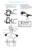
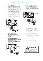
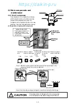
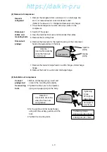
(1) Attaching the gauge manifold
Turn the valve handle of coupler
counterclockwise (the push pin is pulled
up). Slide the sleeve upward, and press it
against the service port. Then, securely
push the valve handle (section A) until a
click sound is heard. After the coupler is
inserted into the service port, release the
sleeve. The coupler is fixed so that it is not
detached from the service port.
Next, turn the valve handle clockwise.
Lower the push pin, and open the check
valve at the service port.
A
Sleeve
Valve handle
Turn the valve
handle
Be sure to use the gauge manifold with
the quick joints shown above.
High pressure side
Low pressure side
HFC134a
(SAE quick joints)
Note: Do not fully turn the valve handle clockwise.
Otherwise, the push pin may be broken.
https://daikin-p.ru


