www.DaikinApplied.com 35
IOM 1210-1 • MAGNITUDE
®
MODEL WMC CHILLERS
o
peraTIon
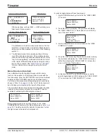
Setpoint Screen, use the following on the VALVE
Setpoint Screen:
a. SP2. Set the VALVE TARGET. This setpoint is
usually 5°F below the minimum fan stage setpoint
established in SP8 of the TOWER Setpoint Screen.
This keeps full flow through the tower until the last
fan is staged off. The default for SP2 is 65°F.
b. SP4. Set VALVE DEADBAND. The default of 1.0°F
is a good place to start.
c. SP12. Set the minimum position to which the valve
can go. The default is 10%.
d. SP13. Set the maximum position to which the
valve can go. The default is 100%.
e. SP14. Set the control gain for error. The default is
20.
f. SP15. Set the control gain for slope. The default
is 1.
CAUTION
Setpoints 14 and 15 on the VALVE Setpoint Screen are site
specific, dealing with system fluid mass, component size, and
other factors affecting the reaction of the system to control
inputs. To avoid possible equipment damage, these setpoints
should be set by personnel experienced with setting up this
type of control.
3. If LIFT was selected for fan control, use:
a. SP3. Set the VALVE TARGET. This setpoint is
usually 5 psi below the minimum fan stage setpoint
established in SP12 of the TOWER Setpoint
Screen. This keeps full flow through the tower until
the last fan is staged off. The default for SP3 is 30
psi.
b. SP5. Set VALVE DEADBAND, the default of 1.0
psi is a recommended initial setting.
c. SP12. Set the minimum position to which the valve
can go. The default is 10%.
d. SP13. Set the maximum position to which the
valve can go. The default is 100%.
e. SP14. Set the control gain for error. The default is
20.
f. SP15. Set the control gain for slope. The default
is 1.
CAUTION
Setpoints 14 and 15 on the VALVE Setpoint Screen are site
specific, dealing with system fluid mass, component size, and
other factors affecting the reaction of the system to control
inputs. To avoid possible equipment damage, these setpoints
should be set by personnel experienced with setting up this
type of control.
(III) VALVE STAGE: Tower staging with bypass valve
controlled by fan stage
A. TOWER Setpoint Screen
1. Use all of the same setpoint settings as those outlined
in section I.A [the TOWER Setpoint Screen section for
control strategy (I) NONE] except for SP2. For SP2,
select VALVE STAGE. .
B. VALVE Setpoint Screen
1. Use all of the same setpoint settings as those outlined
in section II.B [the VALVE Setpoint Screen section for
control strategy (II) VALVE SP]. In addition, set the
following:
a. SP6. Set STAGE UP (valve position % open)
above which the first fan can stage on. Fan
STAGE#X ON temperature from SP8-11 on the
TOWER Setpoint Screen and FAN STAGE UP
TIME from SP4 on the TOWER Setpoint Screen
must also be satisfied. The default for SP6 is 80%.
b. SP7. Set STAGE DOWN (valve position % closed)
below which the first fan can stage off. Fan
STAGE#X ON temperature form SP8-11 on the
TOWER Setpoint Screen and FAN STAGE DOWN
TIME from SP5 on the TOWER Setpoint Screen
must also be satisfied). The default for SP7 is 20%.
(IV) VFD STAGE: Fan VFD, no bypass valve
A. TOWER Setpoint Screen
1. Use all of the same setpoint settings as those outlined
in section I.A [the TOWER Setpoint Screen section
for control strategy (I) NONE] except for SP2. For
SP2, select VFD STAGE for control of the VFD speed
based on temperature or lift.
(V) VALVE SP/VFD STAGE: Fan VFD, no bypass valve
A. TOWER Setpoint Screen
1. Use all of the same setpoint settings as those outlined
in section I.A [the TOWER Setpoint Screen section for
control strategy (I) NONE] except for SP2. For SP2,
select VALVE SP/VFD STAGE.
B. VALVE Setpoint Screen
1. Use all of the same setpoint settings as those outlined
in section II.B [the VALVE Setpoint Screen section for
control strategy (II) VALVE SP].


