15
IOM 1297
WWW.DAIKINAPPLIED.COM
ELECTRICAL
Electrical
Field Power Wiring
The standard power wiring connection to Magnitude chillers is
single-point for WMT models. Power conduit entry will be at the
side of the unit power panel; see
for general reference
as power entry cover plate location will vary by unit configuration.
Copper wiring must be used for power wiring. Refer to the unit
nameplate and the Daikin Tools selection report for the correct
electrical ratings.
DANGER
Qualified and licensed electricians must perform wiring. An
electrical shock hazard exists that can cause severe injury or
death.
Figure 13: Unit Power Connection Point
NOTICE
Top entry is only allowable under certain conditions. Contact
factory for assistance.
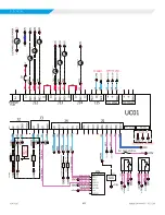
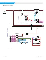
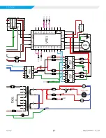
The field control wiring required varies depending on unit model.
See the field wiring schematic for wiring information. These wiring
diagrams are also provided with the chiller.
NOTICE
Wiring, fuse, and wire size must be in accordance with the
National Electrical Code
®
(NEC). The voltage to these units must
be within ±10% of nameplate voltage (415V units must have
voltage within -13% and +6% of nameplate voltage) and the
voltage unbalance between phases must not exceed 2%. Since
a 2% voltage unbalance will cause a current unbalance of 6 to 10
times the voltage unbalance per the current version of the NEMA
MG-1 Standard, it is most important that the unbalance between
phases be kept at a minimum.
CAUTION
Do not use power factor correction capacitors with WMT chillers.
Doing so can cause harmful electrical resonance in the system.
Correction capacitors are not necessary since VFDs inherently
maintain high power factors.
Use with On-Site Generators
All Magnitude Model WMT chillers have their compressors
operated with variable frequency drives and can be used in
applicatinos where they may be required to run with an on-site
electrical generator. This is helpful when the generators are used
for temporary power when the utility power is lost.
Generator Sizing
Natural gas and diesel generators are sensitive to the peak
current loads of the chiller. Although the normal VFD start
sequence does not require these peak values of current,
certain dynamic conditions such as changes in water flow and
temperature or momentary power interruptions can cause high
peak electrical currents. Use the electrical data either on the VFD
data plate or supplied with the chiller performance rating sheet
– obtained from the Daikin Applied sales office – for generator
sizing purposes. The referenced data will show the RLA and
LRA. It is important to size the generator to handle the LRA
value.
WARNING
Generator must be sized by an electrical engineer familiar with
generator applications.
Transfer Back to Grid Power
Due to the special VFD incorporated in all WMT chillers and the
system’s inherent ride-through capabilities, transfer from grid
power to stand-by generator power and back to grid power can
be done at any time. The duration of power interruption during
the transfer process will determine how the chiller will respond.
While the compressor rotor is still spinning at adequate speed,
power is generated internally to keep the bearings and all control
electronics operating. Power interruptions of various durations
will cause different restart scenarios as described below.
1 .
Short:
Interruptions of only a few seconds will allow a
running compressor to return to operating speed almost
immediately. (NOTE: If the operating pressure ratio is high
at the time of interruption, there may be a short delay in
return to operating speed.)
2 .
Medium:
For interruptions that cause the compressor to
coast down below about 3500 rpm (but still generating
control power), the compressor will continue coasting to a
stop, and then restart.
3 .
Long:
Once the compressor coasts nearly to a stop,
control power is lost and the controllers must reboot
normally when either grid power or emergency generator
power is reinstated. (NOTE: If the RapidRestore option is
installed, the time required to restart is reduced to only a
few seconds).


