background image

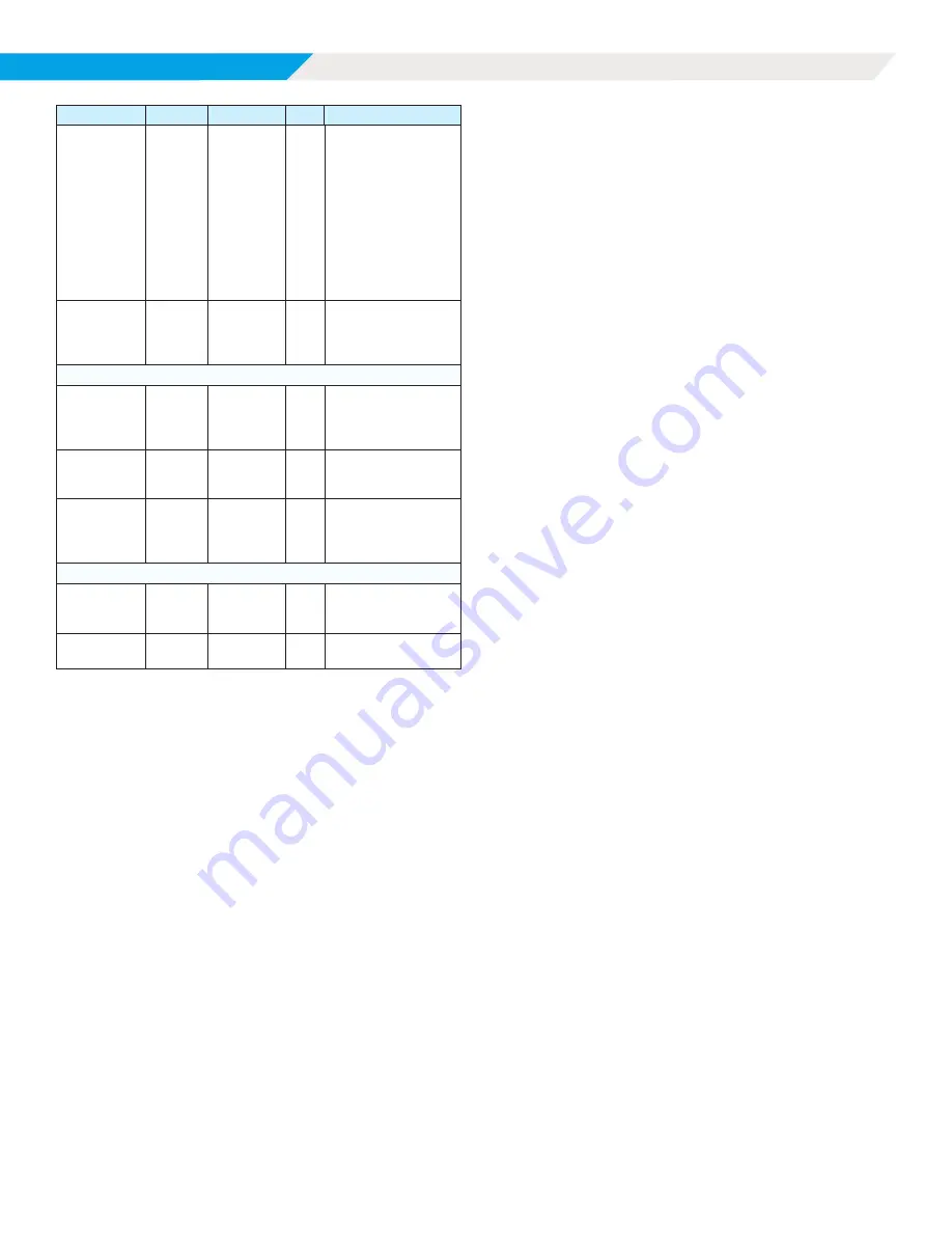
OPERATION

MAGNITUDE WMT CHILLER

DAIKIN  APPLIED

36 

Description

Default

Range

PW

Comments

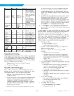
Tower Con-

trol Mode

Auto 

Effi-

ciency

Manual, 

Auto, Auto 

Efficiency

O

Manual: Activate 

manual control of 

tower control outputs 
Auto: Set tower con-

trol outputs to reach 

set point
Auto Efficiency: 

When set point can 

not be reached, 

reduce fan output if 

possible

Response 

Speed

Slow

None, 

Slow, 

Medium, 

Fast

O

Tower control output 

rate of change when 

not on set point

Manual Control

Manual Fan 

Stages

1

0 – 3

O

Set the number of 

running fan stages 

when Manual Con-

trol is enabled

Manual Fan 

VFD

50

0 – 100

O

Set fan VFD speed 

when Manual Con-

trol is enabled

Manual 

Valve / 

Cond Pump 

VFD

90

0 – 100

O

Set bypass valve 

/ cond pump VFD 

when Manual Con-

trol is enabled

Tower Stages
Cooling 

Tower 

Stages

2

1 – 3

O

Number of available 

tower fan stages

VFD Mini

-

mum Speed

0

0 – 70%

O

Minimum tower fan 

VFD speed

Tower Control Setup

Setup for tower control settings in 

Table 17

 will be accomplished 

on the HMI using the Tower screen under Settings. See 

Figure 

32

. Using the chiller unit controller, up to three digital outputs of 

tower staging and two analog outputs (0-10 VDC) are available. 

The two analog outputs are as follows:

1 . 

Bypass Valve or Condenser Pump VFD signal.

2 . 

Tower Fan VFD signal.

Tower Control Strategies

There are four possible tower control strategies that can be 

selected with the Cooling Tower Control (Temp, Lift) and Tower 

Control Mode (Manual, Auto, Auto Efficiency) settings:

1 . 

Manual: Tower control outputs are set to operator 

configured values.

2 . 

Temp, Auto: Tower control is reactive to the delta between 

set point and process value (CEWT), and the process 

value rate of change. This allows the set point to be 

reached by adjusting tower output over time, if possible, 

given the cooling tower capability as well as outdoor air 

temperature and humidity.

3 . 

Lift, Auto: Tower control is reactive to the delta between 

set point and process value (Lift), and the process value 

rate of change. This allows the set point to be reached 

by adjusting tower output over time, if possible, given the 

cooling tower capability as well as outdoor air temperature 

and humidity.

4 . 

Temp, Auto Efficiency: Operates the same as Auto, except 

that when tower fan output is at 100%, after 15 minutes 

has elapsed, tower fan output is slowly reduced until 

CEWT increases to find where increasing tower fan output 

would no longer be effective in reducing CEWT. Fan output 

control will return to normal if the process value increases 

by more than 0.2°F or drops below the set point.

5 . 

Lift, Auto Efficiency can be selected but will operate the 

same as Lift, Auto. Cooling Tower Control by temperature is 

recommended.

For all strategies, the chiller unit controller can control up to three 

tower fan stages, as well as a tower fan VFD and either a tower 

bypass valve or condenser pump VFD. See 

Figure 38

 .

Within each variation of the Auto and Auto Efficiency, a PD loop 

determines a tower capacity loop output (TCLO) value that goes 

from -100 to 100, where -100 is reducing tower capacity as 

quickly as possible, 0 is leaving tower capacity unchanged, and 

100 is increasing tower capacity as quickly as possible.

• 

Tower bypass valve

• 

steps open above 10 TCLO

• 

steps closed below -40 TCLO

• 

Tower fan on/off events limited in frequency by timers for 

staging up and staging down

• 

For a given number N of tower fan stages, all VFD 

controlled:

• 

all stages run at the same speed

• 

VFD speed steps up from minimum speed setting to 

maximum speed setting when above 15 TCLO and 

tower bypass valve position is > 90% of Valve Control 

Range - Max

• 

VFD speed steps down below -5 TCLO

• 

For a given number N of tower fan stages, where one stage 

is VFD controlled:

• 

VFD speed steps up from minimum speed setting to 

maximum speed setting above 0 TCLO and tower 

valve > 90% of Valve Control Range - Max

• 

speed steps down below 0 TCLO

• 

VFD speed -100%/N stages when adding 2nd and or 

3rd stage

• 

VFD speed +80%/N stages when dropping 2nd and or 

3rd stage

• 

For one tower fan stage 

• 

turn on at 90 TCLO if tower bypass valve position is > 

90% of Valve Control Range - Max

• 

turn off at 20 TCLO

• 

For multiple tower fan stages:

• 

(E)nable threshold = 90 / N stages

• 

(D)isable threshold = 20 

Summary of Contents for MAGNITUDE WMT

Page 1: ...IED COM DECEMBER 2023 MAGNITUDE WMT MAGNETIC BEARING OIL FREE CENTRIFUGAL CHILLERS IOM 1297 INSTALLATION OPERATION MAINTENANCE MODEL WMT 350 TO 600 TONS 1200 TO 2200 kW R 1233zd E REFRIGERANT 2023 DAI...

Page 2: ...tion Systems 45 Startup and Maintenance 46 Pre Startup 46 Flow Switch Installation and Calibration 46 Mounting 46 Chiller Maintenance 49 Seasonal Shutdown 50 Seasonal Startup 50 Maintenance Schedule 5...

Page 3: ...ING Polyolester Oil commonly known as POE oil is a synthetic oil used in many refrigeration systems and may be present in this Daikin Applied product POE oil if ever in contact with PVC CPVC will coat...

Page 4: ...c power and control interlocks are required thereby simplifying installation and increasing reliability Necessary equipment protection and operating controls are included All Daikin Applied centrifuga...

Page 5: ...ility of the consignee On units with factory installed insulation the insulation is removed from the vessel lifting hole also used for transportation tie downs locations and is shipped loose It should...

Page 6: ...r for lifting DANGER Improper rigging lifting or moving of a unit can result in unit damage property damage severe personal injury or death See the as designed certified dimensioned drawings included...

Page 7: ...damage severe personal injury or death Refer to as designed certified drawings for weight center of gravity location and details specific to unit configuration Figure 4 Typical Lifting Points Locatio...

Page 8: ...ove the solid state temperature sensor thermostat bulbs and nozzle mounted flow switches from the wells to prevent damage to those components 2 Properly ground the unit or severe damage to the MicroTe...

Page 9: ...es As a safety precaution and to meet code requirements each chiller is equipped with rupture disks located on the condenser and evaporator for the purpose of relieving excessive refrigerant pressure...

Page 10: ...are built and shipped completely assembled with bolt together construction on major components for field disassembly and re assembly on the job site Figure 6 Bolt Together Construction Representative...

Page 11: ...le Compressors and vessels receive an inert gas holding charge All free piping ends are capped Suction and discharge lines have bolt on flanges and if possible remain attached Unit ships with vessel a...

Page 12: ...Installation Magnitude WMT Chiller DAIKIN APPLIED 12 Figure 8 Partial Disassembly Economizer 500T Figure 9 Partial Disassembly...

Page 13: ...13 IOM 1297 WWW DAIKINAPPLIED COM Installation Figure 10 Partial Disassembly Figure 11 Partial Disassembly...

Page 14: ...strated Refer to certified drawings for specific configuration dimensions 2 Unit length represents 2 pass 150 psi water box configuration with grooved connections 3 Unit height represents largest conf...

Page 15: ...ors are used for temporary power when the utility power is lost Generator Sizing Natural gas and diesel generators are sensitive to the peak current loads of the chiller Although the normal VFD start...

Page 16: ...5V SENSOR GND 24V GND BUE1 UE1 IS REPLACED WITH FOR BACNET MODBUS A1 WHT WHT BLK WHT 5V GND SIG LLP PE 5V GND SIG EVPP 5V GND SIG CNDP BLK 3 WHT WHT WHT GND 24V PE Address 1 G G0 Vbat U2 U1 U3 GND U4...

Page 17: ...G CONDENSOR PUMP 1 CP1 Supplied Customer CUSTOMER SUPPLIED POWER 4 20mA LEAVING WATER RESET J5 C1 J3 ETHERNET U2 U3 GND VDC J2 GND 5Vref U1 J12 NO1 U4 GND U5 GND Y1 VG0 VG Y2 Y3 Y4 BMS CARD FIELD BUS...

Page 18: ...PLIED DAIKIN APPLIED 2013 All Rights Reseserved DESCRIPTIO LOCATION INITIAL RELEASE A B C D 8 7 6 5 4 3 8 7 6 5 4 3 UNITBOX 5V GND SIG ECOP 5V GND SIG LEP1 BLK 2 GND 24V Address 1 G G0 Vbat U2 U1 U3 G...

Page 19: ...STANDARD 24V POWER PE PE 24V GND PWR1 BLK 1 PWR1 BLK 2 PWR1 BLK 1 PWR1 BLK 1 PWR1 GRN PWR1 BLK 2 CMPR BOX UTB2 GND 24V PE CMPR BOX UTB2 GND 24V PE A B C D 4 3 2 1 RAPID RESTORE OPTION 24V GND RPS PE P...

Page 20: ...5V GND SIG SCP1 GND G G0 Vbat U2 U1 U3 GND U4 U5 U6 GND U7 U8 U9 U10 GND NO1 C1 2 NO2 NO3 C3 4 5 NO4 C3 4 5 NO5 NO6 NC6 C6 GND J1 J2 J10 J11 J12 J6 BMS J9 5Vref GND Vdc Address 1 MODBUS ON 1234 1234 C...

Page 21: ...T 07 VFD PWRBOX SEE SHEET 05 FROM UNIT BOX ETR3 01 5 D C08 PURGE POWER FAIL PURGE FAULT HARMONIC TEMP SWITCH SEE CC01 C09 SEE CC01 VBUS BLU VBUS ORG VBUS WHT DO NOT CONNECT SHIELD WIRE TO PE HERE SEE...

Page 22: ...OF WORK FOR DAIKIN APPLIED DAIKIN APPLIED 2013 All Rights Reseserved INITIAL RELEASE A B C D 8 7 6 5 4 8 7 6 5 4 MAIN POWER L1 L3 L2 T1 T3 T2 575V 480V TRANSFORMER TX575 L1 T1 HARMONIC FILTER OPT CONT...

Page 23: ...928000 00 9 18 2023 RMT C001517190 WMT500 800T UNIT SCHEM A B C D 4 3 2 1 4 3 2 1 06 07 HARMONIC 575V K3 K4 C 4 C 6 C7 L3 L1 T1 T3 CONTACTOR CNT1 CAPACITOR INPUT OUTPUT BANK TS2 TO VFD POWERBOX 380 48...

Page 24: ...IC FILTER OPTION IS SELECTED R0 AND T0 IS SOURCED FROM THE HARMONIC FILTER BOX G1 NOTE TERMINAL WITH SAME NAMES SHALL BE GROUPED AND JUMPERED TOGETHER PE T0 R0 PFT 11 12 F F FROM MAIN POWER HARMONIC B...

Page 25: ...REACTOR DCR1 PFD A2 A1 L1 R L3 T L2 S L1 R L3 T L2 S GND EMI FILTER OPT G N N 2 L3 G1 G2 120N 31 32 33 34 35 36 37 38 SEC1 SEC2 PRI1 PRI2 2 0 115V 0 115V 1 TX01 FU02 10A 1 2 FU01 10A 1 2 24V GND L PE...

Page 26: ...ile balancing the load Contact a Daikin Applied representative for specific details Single Compressor Units The following sequence of operation applies to Magnitude Model WMT chillers with a single co...

Page 27: ...ressor that is running Variable Fluid Flow Rates Both excessively high and low fluid flow rates should be avoided Extremely high fluid flow rates and high tube velocities will result in high fluid pre...

Page 28: ...ion Another condenser control method is to use a modulating two way control valve located on the outlet connection of the condenser The valve will be nearly closed at startup to restrict water flow wh...

Page 29: ...or the chiller This screen contains the AUTO and STOP buttons in the upper right hand corner which are used to start and stop the unit when in User control mode Other groups of screens can be accessed...

Page 30: ...rm occur This red ALARM button will appear on all screens in the case of an alarm See Figure 25 for an example of an active alarm alert For more information on alarms see page 41 Figure 25 Active Alar...

Page 31: ...up as they are met and also determine why a non start may have occurred Similarly during the shut down process the sequence transitions back to Off and the highlight color will switch to black The lef...

Page 32: ...s such as amp limits 4 TOWER selects the method of controlling the cooling tower and sets the parameters for fan staging VFD 5 VALVE sets the parameters for operation of the expansion valve 6 OFFSETS...

Page 33: ...be selected 5 Additional setpoints can be changed by selecting another setpoint on the screen using the Setpoint Selection buttons or by selecting an entirely new group of setpoints using the Setpoin...

Page 34: ...Max Reset Delta T setpoint if the reset signal equals or exceeds 20 mA The Active Leaving Water variable will vary linearly between these extremes if the reset signal is between 4 mA and 20 mA An exam...

Page 35: ...sor and impeller type Harmonic Filter Amp Rating Factory Set Model De pendent T Based on model of harmonic filter CAUTION Chiller Nameplate RLA MUST match chiller dataplate per compressor Figure 37 Se...

Page 36: ...he set point to be reached by adjusting tower output over time if possible given the cooling tower capability as well as outdoor air temperature and humidity 4 Temp Auto Efficiency Operates the same a...

Page 37: ...ive a BAS can control these components based on the 0 10 VDC signals for the tower fan VFD and tower bypass valve or condenser pump VFD See Figure 39 Figure 39 BAS Tower Control Figure 40 Settings Vie...

Page 38: ...t Stage Suction 0 0 2 to 2 T 2nd Stage Discharge 0 0 2 to 2 T 2nd Stage Suction 0 0 2 to 2 T Figure 42 Settings View Alarms ALARMS Setpoint Settings Description Default Range PW Comments Pressure Alar...

Page 39: ...story files NOTICE The version numbers shown towards the bottom left of the screen are the controllers software identification These numbers may be required by Daikin Applied to answer questions about...

Page 40: ...including manual capacity control While this override is in effect chiller capacity is continuously adjusted to keep the RLA near the limit value Figure 45 Settings View Updater Trend History Screen...

Page 41: ...al alarms that are able to be cleared automatically Clearing an Alarm There are two different indicators that the chiller will generate when conditions arise that are affecting the chiller operations...

Page 42: ...s have been successfully transferred to the USB drive 5 Repeat this process for each desired day of history Each day must be downloaded individually It is not possible to download multiple days of his...

Page 43: ...tion between the compressor controller and the VFD are interrupted MBC Commu nications Fault Communication between the compressor controller and the MBC are interrupted Low Suction Pressure Suction Pr...

Page 44: ...Economizer Pressure Chiller Sealed Gage Transducer 0 5 to 4 5 VDC nominal 14 5 to 21 76 psi EXV Driver Feedback Chiller EXV actu ator 4 to 20 mA Current 0 to 100 Economizer Level Chiller Level Sensor...

Page 45: ...Table 22 Compressor Controller Digital Outputs Description Load Output OFF Output ON 1 VFD Enable VFD Compres sor OFF Compressor ON Table 23 Compressor Controller Analog Outputs Description Output Sig...

Page 46: ...es and differential pressure switches but care must be taken regarding wiring The thermal dispersion flow switch supplied by Daikin Applied shown in Figure 48 comes as a two part unit consisting of a...

Page 47: ...DC signal which is supplied through the switch output of the flow switch for flow indication It is required that the AC and DC commons of power be separated Contact Chiller Technical Response for alte...

Page 48: ...low setpoint while pressing the button increases the flow setpoint Each button press or changes the flow setpoint by 2 5 cm s Step 4 Press the button until LED 9 begins to flash as shown in Figure 54...

Page 49: ...labeled 9 would indicate that the flow was above 230 cm s This may be a normal display depending on range by which flow varies through chiller Figure 56 Display for Flow Above Range Chiller Maintenan...

Page 50: ...caution statement on water quality Seasonal Shutdown WARNING The condenser and evaporator are not self draining Where the chiller can be subject to freezing temperatures the condenser and evaporator m...

Page 51: ...X X Key O Performed by owner personnel X Performed by qualified service personnel 5 year recommendation Harmonic Filter Evaluation If the optional harmonic filter is provided with the chiller measurin...

Page 52: ...0 4 06 52 3 57 54 3 07 56 2 55 58 2 01 60 1 45 62 0 87 64 0 27 66 0 35 68 0 99 70 1 64 72 2 33 74 3 03 76 3 76 78 4 50 80 5 28 Temperature F Pressure psig 82 6 07 84 6 89 86 7 74 88 8 61 90 9 51 92 10...

Page 53: ...d controls wired Wiring complies with National Electrical Code and local codes See Note 4 Condenser pump starting relay CP1 2 installed and wired See Note 3 Miscellaneous Yes No N A Initials Relief va...

Page 54: ...Appendix Magnitude WMT Chiller DAIKIN APPLIED 54...

Page 55: ...arranty shall not apply to products or parts a that have been opened disassembled repaired or altered in each case by anyone other than Company or its authorized service representative b that have bee...

Page 56: ...HANDLERS WATER COOLED CHILLERS AIR COOLED CHI L L ER S M ODU LAR CENTRAL PLANTS SITELINE BUILDING CONTROL S UNIT HEATERS FAN COILS AIR PURIFIERS WATER SOURCE HEAT PUMPS VARIABLE AIR VOLUME UNITS UNIT...

Reviews: