37
IOM 1297
WWW.DAIKINAPPLIED.COM
OPERATION
•
For 2 stages:
• 1 on E*1 TCLO and tower valve > 90%, 2 on E*2
TCLO and tower valve = 100%
• 2 off D*2 TCLO, 1 off D*1 TCLO
•
For 3 3 stages:
• 1 on E*1 TCLO and tower valve > 90%, 2 on E*2
TCLO and tower valve = 100%, 3 on E*3 TCLO and
tower valve = 100%
• 3 off D*2 TCLO, 2 off D*1 TCLO, 1 off D*.5 TCLO
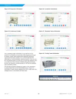
Figure 38: Chiller Unit Tower Control
BAS Tower Control
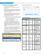
In the above control strategies, the chiller unit controller is directly
controlling the cooling tower fan stages, variable frequency
drives, and bypass valve. As an alternative, a BAS can control
these components based on the 0-10 VDC signals for the tower
fan VFD and tower bypass valve or condenser pump VFD. See
.
Figure 39: BAS Tower Control
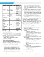
Figure 40: Settings View - Valves
Table 11: Valve Setpoint Settings
Description
Default
Range
PW
Comments
EXV - Capacity Control
EXV Gain
78
20-400
T
Gain selection based
on chiller size and
valve type.
EXV Evap
Weight
1
-100 to
100
1
Weight selection based
on chiller size and
valve type
Figure 41:
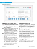
Settings View - Offsets
Condenser
MicroTech
®
Controller
0-10 VDC
Signal
Bypass Line
0-10 VDC Signal
Bypass
Valve
Cooling Tower
Fan Staging
(Up to 2 fans)
Tower
Control
Panel
w/ Fan
VFD
Condenser
MicroTech
®
Controller
Bypass Line
0-10 VDC Signal
BAS
Tower
Control
Panel
w/ Fan
VFD


