49
IOM 1297
WWW.DAIKINAPPLIED.COM
STARTUP AND MAINTENANCE
Step 5:
Once the SP is set, it is recommended that the sensor be
locked to avoid inadvertent readjustment. This can be performed
by pressing both the ‘+’ and ‘-’ buttons simultaneously for 10
seconds. The indication goes out momentarily indicating the unit
is locked. To unlock, the same procedure is performed to toggle
to unlocked.
NOTE:
1. The LED window display on flow switch represents a
velocity range of 50 cm/s. The window centers on the
SP. For example, if the SP was set to 200 cm/s, then
the LED labeled ‘0’ would represent a velocity of 180
cm/s when lit and the LED labeled 9 would represent a
velocity of 230 cm/s when lit.
2. Each LED represents 5 cm/s, or two presses of the
‘+’ or ‘-’ buttons.
3. When power is initially applied to the flow switch, all
green LEDs light and go out step by step. During this
time, the output is closed. The unit is in the operating
mode.
4. When making manual adjustments to the SP, if no
button is pressed for two seconds, the unit returns to
the operating mode with the newly set value.
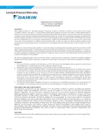
Flow below display range: The SP LED will be lit red and the
leftmost LED will be flashing green. For example, if the SP was
set to 200 cm/s, the flashing labeled ‘0’ would indicate that the
flow was below 180 cm/s. This would be shown if no flow through
chiller or lowered than desired flow.
Figure 55: Display for Flow Below Range
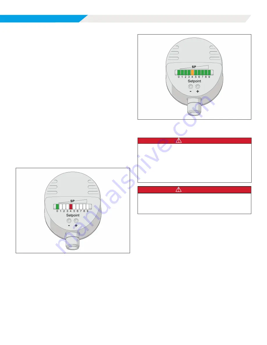
Flow above display range:
The SP LED will be lit amber, all
LEDs to the left and right of the SP LED with be green with the
rightmost LED flashing green. For example, if the SP was set to
200 cm/s, the flashing LED labeled ‘9’ would indicate that the flow
was above 230 cm/s. This may be a normal display depending on
range by which flow varies through chiller.
Figure 56: Display for Flow Above Range
Chiller Maintenance
DANGER
Prevent lint, paper fibers, dust, metallic chips, or other foreign
material from getting into the inverter or accumulating on VFD
cooling outlets, the heat sink, circuit boards, control panels, or
other electrical devices. Failure to do so may affect operation
of the VFD, void warranty, result in a fire, unit damage, property
damage, severe personal injury, or death. Frequently inspect
area around inverter, heatsink, and other electrical devices to
ensure they are free of foreign material.
DANGER
Use approved Lock Out/Tag Out procedures to disconnect power from the
unit. Wait 20 minutes after disconnecting power from the unit before opening
any compressor access covers. The DC link capacitors store enough energy
to cause electrocution.
Electrical System
Maintenance of the electrical system involves the general
requirement of keeping connections clean and tight. Pump
interlocks and flow switches should be checked to be sure they
interrupt the control circuit when tripped.
Cleaning and Preserving
A common cause of service calls and equipment malfunction is
dirt. This can be prevented with normal maintenance. The system
components most subject to dirt are:
1 .
Strainers: Remove and clean strainers in the chilled water
system and condenser water system at every inspection.
2 .
Condenser Tubes: Inspect the condenser tubes annually
for fouling and clean if required. The standard heads
should be removed with care due to their weight. One
method for handling standard heads follows (only qualified
service personnel should perform these tasks):
•
After draining water, remove all but two head bolts at


