IOM 1210-7 • MAGNITUDE
®
MODEL WMC CHILLERS
14 www.DaikinApplied.com
I
nsTallaTIon
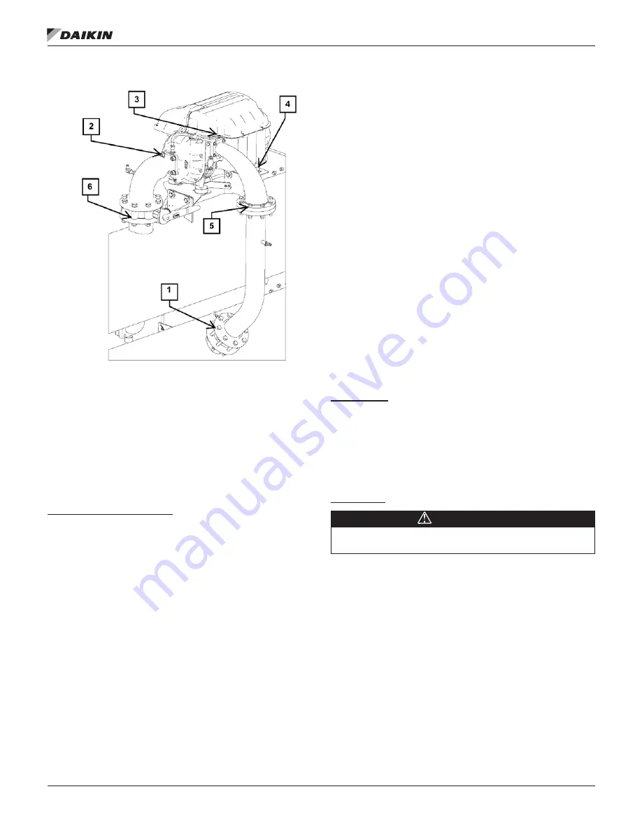
Figure 13:
Compressor Removal / Re-Attachment
2. Remove bolts at discharge elbow connection to
discharge line (flag #5) and install a flange cover.
Warning: Do not loosen bolts at discharge check valve.
(flag #1)
3. Loosen the (4) bolts from the compressor’s bottom
, flag #4).
NOTE:
Do not loosen or remove bolts securing the
compressor brackets as height is pre-set from
the factory.
Compressor Re-Attachment
1. Set compressor on mounting brackets and install the (4)
mounting bolts loosely.
2. Reinstall suction and discharge elbows with new gaskets
and O-rings.
3. Re-attach all associated power wiring and compressor
control cable.
4. Reconnect motor cooling liquid line.
5. Evacuate the evaporator and compressor(s) to 500
microns and perform a standing hold to verify no
moisture or leaks.
6. After verifying that pumps are running and water flow
has been established on both evaporator and condenser,
add vapor refrigerant to bring the saturated temperature
above freezing. Open all valves.
7. Perform refrigerant leak check to ensure all connections
and fittings are securely fastened.
Knockdown Disassembly and
Reassembly Instructions
Type A
Type A units are designed for a wide range of disassembly
and the degree of knockdown varies. Observe the following
recommendations.
1. The chiller is shipped with the full refrigerant charge,
which must be recovered before breaking any refrigerant
connection. Before attempting any disassembly, assume
the condenser isolation valves may have leaked and that
any component of the chiller may be pressurized with
refrigerant. Exert the proper precautions with this caveat
in mind.
2. Check that power has been removed from the unit.
Before disconnecting any wire, it is prudent to label its
function and connection point to facilitate reconnection.
3. The refrigerant charge must be removed from the unit if
the vessels are to be separated.
4. Some insulation repair and touch-up painting may be
required.
5. See Type B instructions for reassembly of components.
Type B
Disassembly
Type B Knockdown units are shipped disassembled except for
the vessel stack and are shipped less refrigerant. If the stack
size or weight dictates further disassembly, the vessels can
be separated by disconnecting any interconnecting wiring and
tubing and then unbolting them. The vessels and compressors
have an inert gas holding charge that must be released prior to
attempting to open any connection.
Reassembly
CAUTION
Standard torque specs must be followed when re-installing
bolts. Contact Daikin Applied service for this information.
1. Reassemble the vessel stack, if disassembled, and
reconnect any wiring and tubing.
2. Mount the compressor(s) on the stack. Be careful to
avoid damaging lines already mounted on the unit.
Mounting bolts, washers and nuts are shipped loose.
Leave the mounting bolts loose until the suction and
discharge lines are installed and aligned.
During assembly, bolts holding block off plates (suction
connection, for example), are used for reassembly of the
component. See
for the location
of the block offs.
3. Do not remove block offs until ready to install piping.
The compressor and vessels have a Schrader valve on
their block off plates to be used for relieving the inert gas
holding charge.


