www.DaikinApplied.com 45
IOM 1210-7 • MAGNITUDE
®
MODEL WMC CHILLERS
o
peraTIon
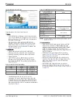
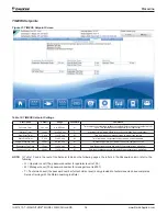
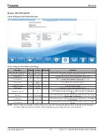
MOTOR Setpoint Screen
Figure 47: MOTOR Setpoint Screen
Table 15: MOTOR Setpoint Settings
Description
Default
Range
Password
Comments
Nominal Capacity
100
0 to 9999 Tons
T
Determines when to shut off a compressor. ONLY applies to multi-chiller setup.
Maximum LWT Rate
0.5 °F/min
0.1 to 5.0 °F/min
M
Inhibits loading if LWT change exceeds the setpoint value
Minimum LWT Rate
0.1 °F/min
0.1 to 5.0 °F/min
M
Additional compressor can start if LWT change is below setpoint
Soft Load Ramp Time [SP7]
5 min
1 to 60 min
M
Time period to go from initial load point (% RLA) set in SP5 to 100% RLA
Initial Soft Load Limit [SP6]
40%
10 to 100%
M
Initial amps as % of RLA, Uses SP4 & 6
Soft Load Enable [SP5]
OFF
OFF, ON
M
Soft load on or off, Uses SP6 & 7
Nameplate RLA * [SP4][
Dependent on dataplate
T
RLA value from chiller data plate
Maximum Amps
100%
10 to 100%
T
% RLA above which loading is inhibited (Load Limit) SP + 5% unloads compressor
Minimum Amps
40%
5 to 80%
T
% RLA below which unloading is inhibited
Demand Limit Enable
OFF
OFF, ON
O
ON sets %RLA at 0% for 4 mA external signal and at 100% RLA for 20 mA signal
OFF – signal is ignored
Harmonic Filter On Threshold
30%
10-100%
M
Min %RLA that the harmonic filter shuts off
Harmonic Filter Off
15%
10-100%
M
Harmonic Filter Engages > 06 RLA%
IGV Lead Start
12%
0 to 100%
T
IGV Position for lead compressor start.
IGV Lag Start
40%
0 to 100%
T
IGV Position for lag compressor start
Lead Start Speed
25%
0 to 100%
T
Select percentage of available speed range.
Lag Start Speed
0%
0 to 100%
T
Select percentage of available speed range.
NOTE:
Setpoints that have a technician level password (T) should only be changed by a Daikin Applied technician. Contact a
Daikin Applied service representative for more information.
CAUTION
* Chiller Nameplate RLA
MUST
match chiller dataplate per compressor.

