www.DaikinApplied.com 47
IOM 1210-7 • MAGNITUDE
®
MODEL WMC CHILLERS
o
peraTIon
MODES Setpoints
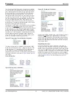
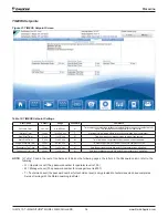
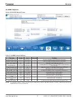
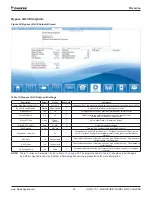
Figure 48: MODES Setpoint Screen
Table 16: MODES Setpoint Settings
D
escription
Default
Range
Password
Comments
Compr # 2 Stage Sequence #
1
1,2, … (# of
Compressors)
M
Sets sequence number for # 2 compressor. If set to 1, it is always first to start.
If set to 2, it is always second to start. (Note 1)
Compr # 2 Staging Mode
Normal
Normal, Efficiency,
Pump, Standby
M
Normal uses standard sequencing, Efficiency starts one compressor on
each unit, Pump starts all compressors on one chiller first, Standby uses this
compressor only if another fails
Compr #1 Stage Sequence #
1
1,2, … (# of
Compressors)
M
Sets sequence number for # 1 compressor. If set to 1, it is always first to start.
If set to 2, it is always second to start. (Note 1)
Compr #1 Staging Mode
Normal
Normal, Efficiency,
Pump, Standby
M
Normal uses standard sequencing, Efficiency starts one compressor on
each unit, Pump starts all compressors on one chiller first, Standby uses this
compressor only if another fails
Maximum Compressors ON
2
1-8
M
Total number of compressors allowed to run at one time
BAS Network Protocol
MODBUS
None, Local, BACnet,
LonWorks, MODBUS,
Remote
M
Sets BAS Standard Protocol to be used, or LOCAL if none
Condenser Pump
Pump #1
Only
Pump #1 Only, Pump
#2 Only, Auto Lead, #1
Primary, #2 Primary
M
Pump #1 Only, Pump #2 Only, use only these pumps AUTO, balance hours
between #1 and #2 #1 Primary, #2 Primary, if primary fails, use other
Evaporator Pump
Pump #1
Only
Pump #1 Only, Pump
#2 Only, Auto Lead, #1
Primary, #2 Primary
M
Pump #1 Only, Pump #2 Only, use only these pumps AUTO, balance hours
between #1 and #2 #1 Primary, #2 Primary, if primary fails, use other
Control Source
Switches
Switches, Local, BAS
O
Sets control source. See
"Unit Enabling/Disabling" on page 29
.
Unit Enable
OFF
OFF, AUTO
O
OFF: everything is off. AUTO: Evap pump on, comp, cond pump and tower on
as required to meet LWT
Unit Mode
COOL
COOL, HEAT
O
COOL, HEAT [Templifier]: Maintains LWT at WATER-SP.
Power Loss Re-Start
OFF
ON, OFF
O
ON= clears timers, enables pumps, and clears power loss alarms
Invert Digital Input
No
No Invert
M
Quick Off (All Off)= 0-24 VAC. External Unit Fault Input= Configurable
Analog Output
Tower
Reset
Bypass Valve, Tower
Fan VFD, Tower Reset
M
Sets tower control using 0-10 VDC
Relay #1 and #2
Configurable
M
Relay #1: Evap Water Pump #2, Relay #2: Cond Water Pump #1
NOTE: If both compressors have the same sequence number, they will automatically balance starts and run-hours.

