OM 1077-1 • MAVERICK I 22 www.DaikinApplied.com
u
ser
I
nTerfaCe
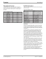
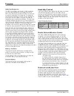
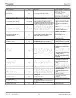
Cooling Differential, Heating Differential, and
DeadBand
Differential is the maximum difference allowed between
the temperature reading and set point before the control
considers a valid demand for cooling or heating. The
differential is also valid for determining that the unit has
satisfied demand. Depending of the mode of operation, the
differential will either be added or subtracted from the set
point to determine those points.
Dead band is the difference between cooling set point
minus cooling differential and heating set point plus heating
differential.
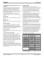
Min DAT Spt
The Minimum DAT set point is used to create warnings in the
system.
Max DAT Spt
The Maximum DAT set point is used to create warnings in the
system.
Stpnt Adj Enable
If the set point adjustment is enabled, then the control will
consider the hardwired potentiometer input to determine
occupied set points only. If the remote set point adjustment is
enabled but the input reads an invalid number, the control will
default back to the occupied set point selection.
Set Point Adjust
This is the actual reading of the potentiometer set point “Stpnt
Adj Enable”.
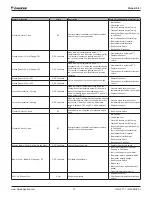
Cooling Lockout Temperature
If the outdoor air temperature is below the cooling lockout
temperature the control will prevent the operation of
mechanical cooling. The default cooling lockout temperature
is 35°F with a range of adjustment from 30°F to 50°F and
the cooling lockout resets at 5°F above the set point. As an
example, if the setting is 40°F and the compressors are not
operating due to low outdoor air temperature, then the DDC
Controller will only allow the operation of mechanical cooling
again once the OAT reading exceeds 45°F.
Heating Lockout Temperature
If the outdoor air temperature is above the heating lockout
temperature the control will prevent the operation of heating.
The default heating lockout temperature is 90°F with a range of
adjustment from 70°F to 90°F and the heating lockout resets at
5°F below the set point.
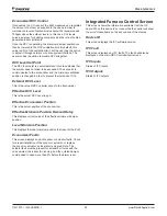
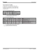
Economizer
This screen shows the information available from the
Economizer. When this device is not connected, the control will
show the word “Unavailable” on the second line of the display.
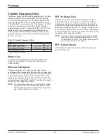
The Economizer uses controllable dampers to increase
the amount of outside-air intake into the building whenever
enabled and whenever outside air enthalpy is favorable for
conditioning the ambient.
The DDC Controller board communicates to the Economizer
Logic Module (ELM) via RS485. Once the ELM receives
communication from the main control indicating a cooling
demand, the ELM will calculate the outdoor air enthalpy
and determine if the economizer operation is favorable for
conditioning the ambient. The main control will read the status
of the economizer and determine whether it is a valid stage for
cooling or not.
If mechanical cooling is active and the enthalpy is favorable
for ELM operation, the DDC Controller will override the
Economizer opening the damper 100%. ELM will regain
control of the damper whenever mechanical cooling is no
longer necessary.
If operating from a thermostat, the Economizer is the first stage
of cooling. If the unit has two compressors available, the second
stage will never be active as long as free cooling is available.
When the DDC Controller is operating from its local temperature
sensors, the Economizer is also a first stage of cooling, if free
cooling is available. First and second stages of mechanical
cooling may be necessary for satisfying the demand in case the
temperature trend towards the set point is not large enough.
Whenever mechanical cooling is active, DDC Controller
overrides the Economizer, opening the damper 100%.
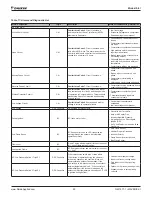
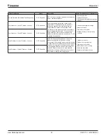
Table 11: Demand Control Ventilation
Economizer
Adjustable Range
Default Setting
Econ. Status
Economizer OK /
Economizer Not OK
Econ. Status
Diff Enthalpy /
Single Enthalpy
Econ. Status
Exh. Fan is ON/OFF
* Enthalpy Setpt.
A/B/C/D/E
A
Eff.Mix.Air Temp
XXX.X °F
* Mixed Air Setpt.
0 – 99
45
Ext.Mix.Air Temp
* Econ. Vent. Limit
0 – 100
0
* Econ.Exh. ON/OFF
0 – 100
50
* Econ. DCV Limit
0 – 100
0
DCV Control
Enabled / Disabled
Disabled
* DCV Level Setpt.
500 – 2000 ppm
700
Ext. DCV Level
Eff. DCV Level
Eff.Eco.Position
Eff.Min.Position
Local. Min. Pos.
Econ. Faults
DCV Sensor Fault
OAE Sensor Fault
RAE Sensor Fault
MAT Sensor Fault
Econ Firm Vrsn
0103
* Menus that are user adjustable


