u
ser
I
nTerfaCe
www.DaikinApplied.com 27
OM 1077-1 • MAVERICK I
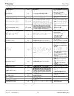
Indoor Relative Humidity
If humidification control is enabled and an indoor relative
humidity sensor is connected, this is the actual indoor relative
humidity measured by the sensor. The actual voltage output
from the indoor relative humidity sensor can be read on “field-
configurable input #2”.
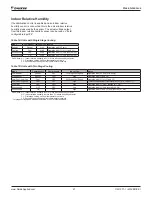
Table 14: Units with Single Stage Cooling
Mode
Compressor 1 Indoor Fan Notes
Reheat
Reheat
High
Operates with (H1 only)
Cooling
Cool
High
Operates with (Y1) or (Y1 and H1)
Economizer1
OFF
High
Operates with (Y1) only, ignores (H1)
Economizer2
ON
High
Operates with (Y2) only, ignores (H1)
Definitions: H1 - Indoor relative humidity is 2% or more above humidity set point
Y1 - First stage cooling call from thermostat or network
Y2 - Second stage cooling call from thermostat or network
Table 15: Units with Two Stage Cooling
Mode
Compressor1
Compressor2
Indoor Fan
Notes
Low Reheat
Reheat
OFF
*1st Stage Cool Speed
Operates with (H1 only) or (H2 only)
High Reheat
Reheat
Cool
High
Operates with (Y1 and H2)
Low Cool – Low Fan
Cool
OFF
*1st Stage Cool Speed
Operates with (Y1) or (Y1 and H1)
Low Cool – High Fan
Cool
OFF
High
[Future Enhancement] Operates with (Y1) or (Y1 and H1)
High Cool
Cool
Cool
High
Operates with (Y2) call – ignores (H1, H2)
Economizer1
OFF
OFF
Low
Operates with (Y1) only, ignores (H1, H2)
Economizer2
ON
OFF
High
Operates with (Y1 and Y2) only, ignores (h1, H2)
Definitions: H1 - Indoor relative humidity is 2% or more above humidity set point
H2 - Indoor relative humidity is more than 5% above humidity set point
Y1 - First stage cooling call from thermostat or network
Y2 - Second stage cooling call from thermostat or network
*1st stage cooling speed has a default value of 50% of high fan speed


