


OM 1077-1 • MAVERICK I 34 www.DaikinApplied.com
q
uICk
s
TarT
q
uICk
s
TarT
Units with Thermostat Control
Connect Room Thermostat (and Time Clock if used) to DDC
Controller rooftop unit controller circuit board. Follow Unit
Installation Instructions obeying all safety guidelines. Replace
any low voltage shields removed during the installation of the
thermostat wires.
Connect line voltage power wires to the appropriate main
power terminal block or disconnect. Connect gas lines for
heater section (if applicable).
Apply power to Rooftop Unit.
Using Keypad and Display on DDC Controller circuit board,
take unit from “OFF” mode to “Control By Thermostat” by
following numbered instructions below. Refer to
Check for any alarms on DDC Controller display. If any alarms
are present, find the source and clear the alarm condition.
Scroll through the DDC Controller display using the keypad
and set to Runtest mode. Choose either Heating or Cooling
runtest. Enter the password to start Runtest. Refer to
.
Record temperatures and refrigerant pressures (if applicable)
during the runtest. Check for any alarms on the DDC Controller
display. If any alarms are present, find the source and clear the
alarm conditions.
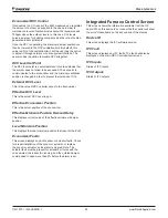
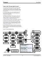
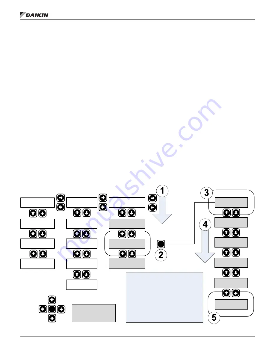
Figure 11: Quick Start Menu Steps
GENERAL
INFORMATION
Software Version
*.**
ALARMS
******
System Config
********
UNIT STATUS
MODE
STANDBY
24VAC INPUTS
Y1 OFF
OUTPUTS
Compressor 1 OFF
CAPACITY
*********
EFFECT.OCCUPANCY
Occupied
OCCPCY OVERR SP
Manual Occupied
OCCUPIED MODE
OFF
IND FAN OCCUPCY
Cont when occup.
All Sub-Menus
highlighted gray are
user adjustable
OCCUPIED MODE
OFF
OCCUPIED MODE
AUTO
OCCUPIED MODE
FAN ONLY
OCCUPIED MODE
HEAT ONLY
OCCUPIED MODE
COOL ONLY
OCCUPIED MODE
Ctrl by Tstat
1. Scroll over and down to
“OCCUPIED MODE”
2. Briefly press [Enter]
3. Wait until cursor on display flashes
4. SCROLL DOWN
5. Chose Ctrl by Tstat
6. Briefly press [Enter]
7. Wait until cursor stops flashing
[ENTER]
UNIT
KEYPAD


