


I
nTroduCTIon
www.DaikinApplied.com
5
OM 1077-1 • MAVERICK I
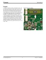
Figure 1: Controller Component Locations
Item
Description
P1
Electric heat connector
Fan
Indoor blower motor connector
CC1
Compressor 1 connector
CC2
Compressor 2 connector
P3
Reversing valve 1, Reversing valve 2, Outdoor Coil temperature sensor 1, Outdoor Coil temperature sensor 2, Outdoor Fan 1, and Outdoor
Fan 2 connector
P4
Motorized Fresh Air Damper, Economizer Logic Module (ELM), and Smoke Detector connector
P5
Return air temperature sensor, Fan proving switch, Clogged filter switch, and Discharge air temperature sensor connector
P6
Freeze sensor 1, Freeze sensor 2, Outside air temperature sensor, High pressure switch 1, High pressure switch 2, Low pressure switch 1,
and Low pressure switch 2 connector
P10
RJ11 connector for factory run test
P11
Configurable pins used to set unit type
P12
Test Pins to force defrost for heat pump models
P13
Connector to Integrated Furnace Control (IFC) – provides power and communication between DDC Controller and IFC
T7
Field Installed Space Temperature Sensor with Set Point and Override, Field configurable 1, and Field configurable 2 terminal block
T14
Not supported
T81
Thermostat screw terminals Common terminals Terminals used for 24 volt common connections & power supply
24 Volt terminals
Terminals used for 24 volt hot connections & power supply
Comfort Alert
Terminals used to connect a Comfort Alert module
LED4
LED4 is blinking when the control has an ALARM present, solid when power is applied.
MOD1 LED
MOD1 LED blinks when the control is communicating on the internal network between the IFC and/or economizer
MOD2 LED
MOD2 LED blinks when the control is communicating between the DDC Controller and field installed communication card
P1
Common
24 VAC
P3
P4
P5
P11
Keypad
LED 4
MOD1
P10
T14
MOD2
P12
T7
T81
Fan, CC1, CC2,
Common
Comfort Alert
LCD Display
P6
P13


