OM 1077-1 • MAVERICK I 8 www.DaikinApplied.com
C
onTrol
I
npuTs
and
o
uTpuTs
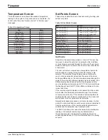
Control Outputs
Table 3: Control Outputs
Item Description
Type
Option
1
CC1 - Compressor output 1
24VAC 1.5A @ 24VAC, pilot duty
2
CC2 - Compressor output 2
24VAC 1.5A @ 24VAC, pilot duty
3
W1 - Heat output
24VAC 1.5A @ 24VAC, pilot duty
4
W2 - Heat Output
24VAC 1.5A @ 24VAC, pilot duty
5
G - Fan Output
24VAC 1.5A @ 24VAC, pilot duty
6
L - thermostat signal
24VAC 25mA loading
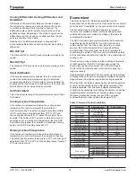
Table 4: Thermostat Options
Device
Part Number Description
Stand alone 24V thermostat /
touch screen
113129801
Up to 2-heat / 2-cool
Stand alone 24V thermostat
113129901
Up to 2-heat / 2-cool
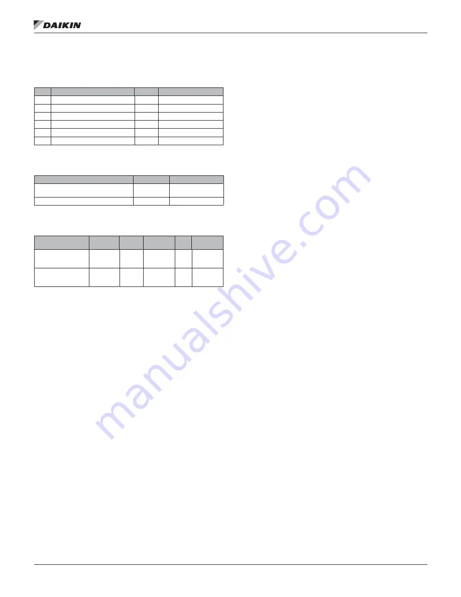
Table 5: Zone Sensor Module Wire Guide
Device
Part
Number
Wire
Gauge Conductors Type Listings
Wall mounted sensor
with tenant override
113117701
18
3
Solid
18 AWG
3/C CL2P
Thermostat
Wall mounted sensor
with space point
adjustment
113117701
18
3
Solid
18 AWG
3/C CL2P
Thermostat
Control Output Descriptions
(1) CC1 - Compressor output 1.
The DDC Controller can
control the compressor contactors. The DDC Controller can
monitor the system and respond to system faults and comfort
alert inputs to shut down the compressors in the event of a
failure.
(2) CC2 - Compressor output 2.
The DDC Controller can
control the compressor contactors. The DDC Controller can
monitor the system and respond to system faults and comfort
alert inputs to shut down the compressors in the event of a
failure.
(3) W1 - Heat output.
The DDC Controller has two outputs to
control resistance electric heat.
(4) W2 - Heat Output.
The DDC Controller has two outputs to
control resistance electric heat.
(5) G - Fan Output.
The DDC Controller can control the indoor
fan by use of a fan relay.
(6) L - Thermostat signal.
The “L” terminal will output a
flash code to an indoor 24 V thermostat equipped with an “L”
terminal.


