s
equenCe
of
o
peraTIon
www.DaikinApplied.com 13
OM 1077-1 • MAVERICK I
s
equenCe
of
o
peraTIon
IMPORTANT
The DDC Controller is shipped with the control disabled so units do not
accidentally energize during installation. The commissioning of the rooftop
unit therefore requires the configuration of the Occupied Mode menu prior
.
Cooling
When the DDC Controller receives a call for cooling via
thermostat or zone sensor compressor 1 energizes. After the
indoor fan on delay (1-180 sec / default 10 sec) the indoor fan
energizes. The indoor fan on delay starts when the call for
cooling is initiated.
When used in local zone sensor mode of operation, the DDC
Controller satisfies the set point using all or a partial number
of stages available. When cooling demand exists, the DDC
Controller will stage up in the following order: Economizer, First
Stage Cooling, and Second Stage Cooling based on demand.
When used in local thermostat mode of operation, the DDC
Controller allows the thermostat to control the demand for
cooling. When cooling demand exists, the DDC Controller
will stage up in the following order: Economizer, First Stage
Cooling. Only two stages will be allowed to energize, so if the
economizer is active then the first stage mechanical cooling will
become second stage and second stage mechanical cooling
will not be used.
Heat
When in heating mode of operation, the DDC Controller
satisfies the set point using all or a partial number of stages
available. When heating demand exists, the DDC Controller
will utilize heat sources in the following order of priority as
available: Gas Heat and Electric.
When the heat demand requires multiple heating outputs at
the same time, a minimum staging delay of 5 seconds between
energizing and de-energizing heating outputs is necessary to
prevent the inrush current startup of multiple loads. The inter
stage is adjustable between 5 and 50 seconds.
The source of demand, like the other modes of operation, is a
result of one of either thermostat or remote sensors.
Integrated Furnace Control
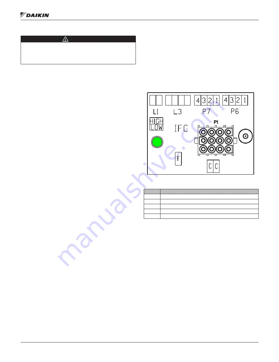
The Integrated Furnace Control (IFC) is external to the DDC
Controller, and on units so equipped, controls the furnace and
gas valve operation based on signals from the DDC controller.
The IFC also provides furnace troubleshooting information via
LED flashing fault codes. When a fault condition exists, the
LED (see
) flashes the number of times indicated by
the code number, pauses, and repeats.
Figure 7: Integrated Furnace Control Status LED
Table 6: Integrated Furnace Control Fault Codes
Code
Meaning
1
Failure To Detect Or Sustain Flame
2
Pressure Switch Or Inducer Problem Detected
3
High Limit Protection Deice Open
4
Gas Valve Not Energized Or No “W” Signal
5
Flame Toll Out Switch Open
Call for Heat
After a call for heat the IFC checks to ensure the high
temperature limit and rollout switches are closed. If either
is open, the IFC responds with a fault code. If high limit and
rollout switches are closed, the IFC checks that both pressure
switches are open. If either pressure switch is closed, the
IFC will respond with a fault code and it will flash code “2”
on the LED, waiting indefinitely for both pressure switches to
open. If both pressure switches are open, the IFC proceeds
to prepurge.
LED


