English /
8
Care and Cleaning
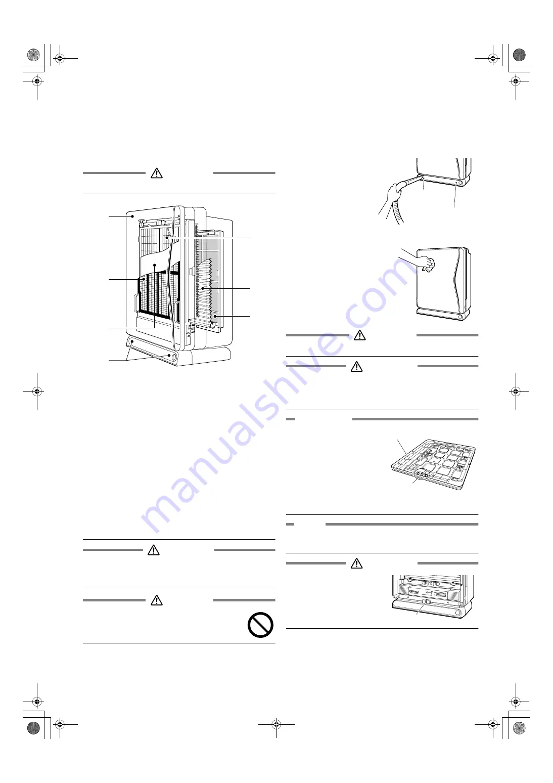
Cleaning chart
For cleaning, remove each part in the number order.
For restoring each part, follow the opposite order.
CAUTION
•
Stop operation and pull the power plug before cleaning.
1 Front panel
(page 8.)
If gets dirty;
wipe off
2 Pre-filter
(page 9.)
Once in two weeks;
clean
3 Bio-antibody filter
(page 9.)
1 year after opening;
replace
Unwashable
4 Plasma ionizer
(pages 11, 12.)
If the cleaning sign blinks;
• Opposing pole plate;
soak
• Streamer discharger;
soak
• Ionizing frame (Ionized wire);
soak
5 Pleated filter
(page 10.)
If the replacement sign turns on or blinks;
replace
6 Deodorizing catalyst unit
(page 15.)
If it gets dirty, without removing from the main unit;
vacuum
Unwashable
7 Air inlet for the dust/odor sensor
(page 8.)
If clogged;
vacuum
WARNING
During maintenance you must stop the operation and
remove the power plug from the electrical outlet.
Electric shock or injury may occur.
CAUTION
Do not wash the main unit with water.
If water gets inside the unit, electric shock or
malfunction may occur.
Cleaning the air inlet for the dust/odor
sensor
• Clean dusts clogged in
the air inlet for the dust/
odor sensor.
• Use crevice nozzle of a
cleaner for cleaning.
Cleaning the front panel
• Wipe off the dirt with a
cloth or tissue slightly
soaked with water.
• In the case of heavy dirt,
wipe it off with a cloth
soaked with mild
detergent.
CAUTION
•
Do not use hard sponge. Scratch may result.
WARNING
•
Do not use gasoline, benzene, thinner, polishing powder, kerosene
or alcohol. Crack, electric shock or fire may result.
•
Do not rinse the main unit. Electric shock, fire or breakdown may
result.
ATTENTION
•
Be careful not to scratch the
front or damage the rear
protrusions of the removed
front panel.
In particular, the rear
protrusions function as a
safety switch to turn OFF the
power if the front panel is
opened.
If damaged, the unit will not
operate.
NOTE
If the front panel is not correctly set on the main unit,
the unit will not operate.
WARNING
•
Do not touch the safety switch
on back of the hole on bottom of
the main unit.
Electric shock may result.
1
4
5
6
2
3
7
Air inlet for the
dust sensor
Air inlet for the
odor sensor
Bottom hole
01_EN_3P167171-3E.fm Page 8 Monday, August 7, 2006 6:45 PM


