background image

I

nTroduCTIon

www.DaikinApplied.com 

IM 968-4 • MICROTECH III CHILLER UNIT CONTROLLER

Bus Termination

Bus termination resistors are used for properly terminating 

a network based on twisted pair cabling with attention to 

impedance. 

NOTE: 

Refer to Echelon 

L

on

W

orks

 FTT-10A Transceiver 

User’s Guide for details regarding acceptable 

configurations, cabling requirements, 

terminations, impedance, and other requirements 

(

www.echelon.com

).

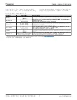
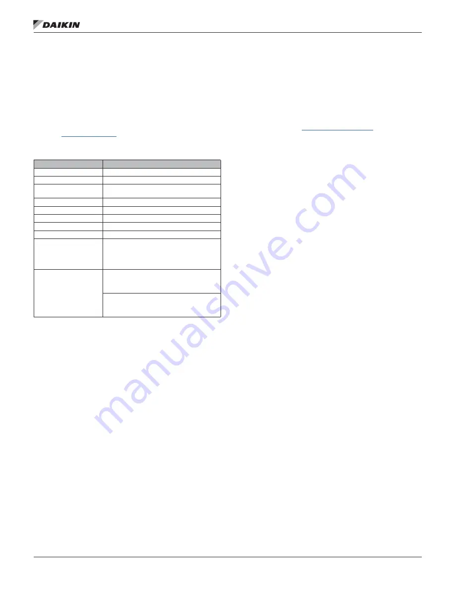
Transmission Specifications

Component

Value

Network topology

Flexible Free Topology 

Neuron chip processor

3150

Free Topology Transceiver 

(FTT-10A)

50051

Cable types

TIA Category 5 (recommended)

Maximum cable length

1476 ft (450 m) per segment (total of all lines)

Maximum node separation 820 ft (250 m)

Data transmission

Two-wire, half duplex

Data transmission rate

78 kbps (baud)

Bus terminator

Free topology: use one (1) 52.3 

 bus terminator 

at the busiest point of the network 
Daisy chain or standard line (dual) topology: use 

two (2) 105 

 bus terminators at the end of both 

network segments

Repeaters and routers

Repeaters and router are typically used when the 

entire cable length in a given segment exceeds 

1476 ft (450 m) in a free topology or 2953 ft 

(900 m) in a line topology.
Each trunk can have at maximum one physical 

repeater. Repeaters and routers may not be used 

in a ring topology. They must be placed before 

the network’s ring port.

Software Interface to Unit Controller

The 

L

on

W

orks

 communication module software translates 

the Standard Network Variable Types (SNVTs) and Standard 

Network Configuration Parameter Types (SCPTs) used in 

the MicroTech III chiller unit controller into the variables and 

parameters used by the 

L

on

W

orks

 network. The software 

conforms to the LonMark 3.4 chiller profile. Refer to MicroTech 

III Chiller Unit Controller Protocol Document, ED 15120 for 

additional information (

www.DaikinApplied.com

).

Summary of Contents for MicroTech III

Page 1: ...er Unit Controller LonWorks Communication Module Models AGZ and AMZ Trailblazer Air cooled Scroll Chiller Models AWS and AWV Pathfinder Air cooled Screw Chiller Model ADS Air cooled Global Screw Chill...

Page 2: ...sioning and Configuration 10 LonWorks Network Addressing 10 External Interface File XIF and NXE Files 10 Resource Files 10 Commissioning 10 Configuration 10 Enter Password 11 Set Receive Heartbeat 11...

Page 3: ...on 8040_10 LonMark Functional Profile Chiller Version 1 0 www lonmark org Echelon Corporation 078 0156 01G LonWorks FTT 10A Free Topology Transceiver Users Guide www echelon com Limited Warranty Consu...

Page 4: ...geon blue Housing plastic light gray Operating Temperature 40 158 F 40 70 C Humidity 90 RH Atmospheric pressure Min 10 psi 70kPa corresponding to max 9 842 ft 3 000 m above sea level Storage and Trans...

Page 5: ...ule Attached to Unit Controller Figure 4 shows the important features of the LonWorks communication module which are described in the following section Figure 4 LonWorks Communication Module Main Feat...

Page 6: ...icates the communication status between the LonWorks communication module and the network Table 2 Table 2 BUS LED Activity BUS LED Color Description Green The unit controller is capable of communicati...

Page 7: ...pology use one 1 52 3 bus terminator at the busiest point of the network Daisy chain or standard line dual topology use two 2 105 bus terminators at the end of both network segments Repeaters and rout...

Page 8: ...nication module on the unit controller The communication module can be connected directly to the unit controller itself or to an existing module if one is attached 1 Set the Unit On Off Switch to Off...

Page 9: ...ol panel of the unit This must be done prior to replacing a communication module See for switch location 2 Remove power from the unit controller 3 Locate the LonWorks communication module to the left...

Page 10: ...nication module Resource Files Resource files contain definitions of functional profiles network variables types configuration property types and enumerations Resource files are required for displayin...

Page 11: ...net IP Setup Menu Enter Password 4 Scroll down to View Set Unit and press Enter 5 Navigate to the LON Setup menu on the unit controller keypad display Figure 11 Set Receive Heartbeat 1 Turn the circul...

Page 12: ...Minimum Send Time Controls the minimum period of time that expires before certain network variables can be retransmitted nciMinSendTime can also be used to change these values1 Rcv Heartbeat 0 6553 5...

Page 13: ...ved cable Do not use different wire types on the same bus Follow the bus length limits for the cable type Confirm that you have the correct transceiver Make sure that the network trunk avoids strong s...

Page 14: ...nt to its standard terms and conditions of sale including Limited Product Warranty Consult your local Daikin Applied Representative for warranty details To find your local Daikin Applied Representativ...

Reviews: