background image

OM 1239 

14 www.DaikinApplied.com

• 

The fault terminal (A) energizes while the unit is 
in defrost mode. It will stay energized until the 
temperature recovers to 36°F for standard equipment 
(14.5°F for extended range). A to C will be used to 
indicate an alarm signal. The previous operation of 
heating or cooling determines how the low suction 
temp alarm must be reset. The fan and pump remain 
available for operation.


Cooling mode

When the suction line temperature falls below 28°F standard 
equipment (28°F extended range) in cool mode the:

• 

Compressor de-energizes.

• 

The fan and pump remain available for operation.

• 

Alarm output energizes. 

• 

When the suction line temperature recovers to 36°F 
standard equipment (14.5°F on extended range) the 
low temperature fault continues and the compressor 
will be locked out.


Fan only mode

When the suction line temperature falls below 28°F standard 
equipment (28°F extended range) in cool mode the:

• 

The fan and pump remain available for operation.

• 

Alarm output energizes.

The previous operation of heating or cooling determines 
how the low suction temp alarm must be reset.

• 

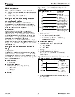
Interstaging timer –

 A default value of 5 minutes 

between staging of compressors, this feature 
minimizes short cycling of compressors and 
improves comfort.

• 

Motorized water valve or pump start

 – When 

there is a call for cooling, dehumidification or 

heating, the MicroTech III unit controller will energize 
its IV/PR (H8) terminal to open the motorized water 
valve or start the loop pump 45 seconds prior to 
starting the compressor. The IV/ PR (H8) terminal 
may be “daisy chained” between 200 units.

• 

Lead compressor fail replacement

 – Upon 

detection of a lead compressor fault and the 
lag compressor is available, the selected lead 
compressor will be “failed replaced” by the lag 
compressor. Lead compressor will immediately be 
de-energized by ignoring the compressor minimum 
ON timer. Lag compressor will energize in place of 
the failed lead compressor, when the lag compressor 
minimum OFF timer has expired. Reversing valve for 
the lag compressor will be positioned, if necessary, 5 
seconds after the lag compressor starts up.

• 

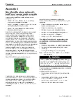
Compressor protection for size 290 


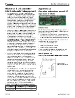
A communications module installed in the 
compressor electrical box provides advanced 
diagnostics, protection and communications, that 
enhance compressor performance and reliability.

Fault status and LED annunciation


High / low pressure faults (HP/LP)

• 

Normally closed high and low pressure 
switches will protect both circuits of the water 
source heat pump from excessively high or low 
refrigerant pressure conditions. The MicroTech 
III monitors these switches individually. If either 
compressor is running and the high pressure 
switch for that circuit opens that compressor 
will shutdown immediately. The MicroTech III 
will enter "compressor faili replace" mode which 
will allow the other circuit to operate normally 
while it is able. If the LP switch remains open for 
either circuit for the Low Pressure Time Delay 
(default is 30 seconds) that compressor will 
shutdown immediately. The MicroTech III will enter 
"compressor faili replace" mode which will allow 
the other circuit to operate normally while it is 
able. If both compressors are off on a high or low 
pressure fault the MicroTech III will go into Fault 
mode and neither compressor is available.

MicroTech III LED Status – High/Low Pressure Faults

Pressure

Yellow

Green

Red

HP

Off

Off

Flash

LP

Off

Off

Solid

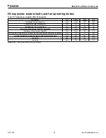
Note: Circuit 2 faults are annunciated on the I/O expan-

sion module.

See Table 9 on page 

19.

When the unit is in high or low pressure fault modes the 
following occurs:

• 

The failed compressor de-energizes.

• 

The fault terminal (A) energizes (fault). A to R will 
be used to indicate an alarm signal.


Low suction temperature fault heating

• 

The control will attempt to recover either circuit from 
a low suction temperature condition by defrosting 
the water heat exchanger(s) (coaxial coil). See 
"Defrost process operation:" on page 

14

 for 

details.

M

ICro

t

eCh

 III u

nIt

 C

ontroller

Summary of Contents for MicroTech III

Page 1: ...MicroTech III Unit Controller with I O Expansion Module for Two Compressor Water Source Heat Pumps Large Capacity Vertical Models LVC Standard Range LVW Extended Range Large Capacity Horizontal Models...

Page 2: ...nd LED annunciation 14 A and IV PR H8 16 Fault recovery and reset 17 Fan operation during most modes faults and shutdowns 19 Faults and modes 19 Microtech III unit controller interface to external equ...

Page 3: ...nication module Each option features direct quick connect wiring to all unit controlled components for clean wiring inside the control box Each control circuit board receives power from a 75VA transfo...

Page 4: ...ubleshooting and diagnosis of the second circuit Allows for Control of second refrigeration circuit LonWorks Communication Module The MicroTech III control system accepts a plug in LonWorks commu nica...

Page 5: ...rsing Valve Common H6 7 Reversing Valve Output H7 1 1 No Connection H7 2 No Connection H7 3 Red LED Output H7 4 Green LED Output H7 5 Yellow LED Output H7 6 Red Green Yellow LED Common H8 1 1 Isolatio...

Page 6: ...OM 1239 6 www DaikinApplied com MicroTech III Unit Controller Figure 1 MicroTech III unit controller terminal locations...

Page 7: ...Economizer Output N O H3 4 Ext 24 VAC Common H3 5 Fan Motor Signal H3 6 Fan Motor Common H4 1 1 Entering Water Temp Sensor Signal H4 2 Entering Water Temp Sensor Common H5 1 1 No Connection H5 2 No Co...

Page 8: ...PI_SELECT1_0 SPI Select To Communications Board CN_SPI 4 SPI_CLK_0 Master Clock CN_SPI 5 SPI_RX_0 MOSI CN_SPI 6 SPI_TX_0 MISO CN_SPI 7 SREADY_0 SPI Ready To Baseboard CN_SPI 8 No Connection TB1 1 TB1...

Page 9: ...re cycling power to the controller or sending a controller a reboot command through the network communications Table 6 MicroTech III controller configuration jumper settings Baseboard Description Jump...

Page 10: ...Open Secondary Heating Options JP3 JP4 JP3 Open None JP4 Open JP3 Shorted Supplemental Electric Heat JP4 Open JP3 Open Boilerless Electric Heat JP4 Shorted Cooling Dehumidification Options JP5 JP6 JP...

Page 11: ...hru activation of the G terminal by the thermostat fan switch on On a further demand for cooling stage 2 the 1st compressor will start in the cooling mode On a further demand for cooling the second co...

Page 12: ...annunciation capabilities Standby mode BACnet or LonWorks units can receive a signal from the Building Automation System BAS to initiate the energy savings mode This mode is typically initiated by the...

Page 13: ...no anti freeze in the cooling heating modes and extended range applications in the cooling mode or 13 5 F LWT on extended range applications in the heating mode those with anti freeze Defrost process...

Page 14: ...r will energize in place of the failed lead compressor when the lag compressor minimum OFF timer has expired Reversing valve for the lag compressor will be positioned if necessary 5 seconds after the...

Page 15: ...condensate overflow mode See Table 10 on page 19 When the unit senses a condensate overflow fault while in cooling mode the following occurs The compressors de energize The fault terminal A energizes...

Page 16: ...rmal operation When the E terminal is no longer grounded the unit will automatically return to normal operation Note The remote shutdown input E will suspend unit operation Disconnect power when servi...

Page 17: ...clears faults the first two times they occur within a 24 hour period and triggers an automatic lockout on the 3rd fault The fault remains active until the alarm is manually cleared At the end of the...

Page 18: ...terminal wiring Refer to MicroTech III unit controller and I O expansion module connector terminal tables and descriptions on page 5 MicroTech III unit controller terminal locations on page 6 3 The le...

Page 19: ...is left on after system check out the unit may be damaged Table 9 Room sensor status LED LED On Time Sec LED Off Time Sec Operating Mode 0 5 0 5 Alarm Condition or Network Wink Operation Active 0 0 Co...

Page 20: ...FF ON Compressor 1 Suction Temp Sensor Fail Fault Flash Flash ON Freeze Fault Detect Fault Flash OFF Flash Compressor 1 Low Suction Temp Fault Flash OFF OFF Room Temp Sensor Fail Room Sensor Control O...

Page 21: ...ostat or control inputs To interface triacs or other solid state switching devices to the MicroTech III unit controller inputs separate them from the board using mechanical relays To do this use the t...

Page 22: ...OFF OFF Flash Compressor 2 Low Pressure LP2 Fault OFF OFF ON Compressor 2 Low Suction Temp LT2 Sensor Fail Fault Flash Flash ON Compressor 2 Low Suction Temp LT2 Fault Flash OFF OFF Entering Water Te...

Page 23: ...is needed the humidistat can be wired to TB1 1 on the Microtech III unit controller allowing the WSHP unit to operate in dehumidification mode only The unit will only respond to a call for dehumidific...

Page 24: ...DC Signal Common Fan Speed Se lect Fan Coil Version Only Emergency Shutdown Unoccupied Dehumidifica tion Sensor Digitally Adjustable Room Temperature Sensor Part No 910121754 Figure 13 MicroTech III b...

Page 25: ...d return air discharge air and leaving water temperature sensor Wall mounted temperature sensors include setpoint adjustment and tenant override The user has the capability of substituting the wall se...

Page 26: ...Four green status LEDs on the communication module indicate communication activity on the MS TP communication network and with the unit controller Figure 15 MicroTech III BACnet MS TP snap in communic...

Page 27: ...4V NO 24VAC COMMON 24V NC Note Switch L2 L3 fan motor wires for left hand unit Legend Item Description CC1 Circuit 1 Compressor Contactor CC2 Circuit 2 Compressor Contactor CM1 Circuit 1 Compressor CM...

Page 28: ...OOL 2 W1 HEAT 1 W2 HEAT 2 A ALARM OUTPUT 5 DC SIGNAL COM 4 ROOM SENSOR TO 3 SETPOINT ADJUST 2 FAN MODE HT CL AUTO 1 ROOM SENSOR LED U MARK IV OCC UNOCC E EMER SHTDN INPUT R 24VAC Communication Module...

Page 29: ...Switch L2 L3 fan motor wires for left hand unit Note Wiring diagrams are typical For the latest drawing version refer to the wiring diagram located on the inside of the controls access panel of the un...

Page 30: ...HTDN INPUT R 24VAC Communication Module MicroTech III Controller 24V NO 24VAC COMMON 24V NC Note Switch L2 L3 fan motor wires for left hand unit Note Wiring diagrams are typical For the latest drawing...

Page 31: ...oose connection Check for faulty compressor capacitor Insufficient cooling or heating Check for lock rotor amp draw Check for defective compressor internal windings with ohm meter Check for proper air...

Page 32: ...t to its standard terms and conditions of sale including Limited Product Warranty Consult your local Daikin Applied Representative for warranty details To find your local Daikin Applied Representative...

Reviews: