


OM 1239
15 www.DaikinApplied.com
■
Low suction temperature fault cooling
•
When the suction line temperature falls on a
circuit below 28° F this disables the compressor of
that circuit only.
•
The fan will continue to run drawing warmer air
over the air heat exchanger.
•
When the suction line temperature increases
by Low Temp Protect Diff (the default is 8° F)
degrees.
•
The compressor is available for cooling if the
Compressor Minimum Off timer has expired.
•
Mark the occurrence of the fault.
MicroTech III (circuit 2) LED Status – Low Suction Line Temperature Fault
Yellow
Green
Red
Flash
Off
Off
■
Low voltage brownout protection
When in brownout condition, thermostat and control inputs
have no affect upon unit operation. Remote shutdown and
brownout conditions have the same level of priority. See
Table 10 on page
19.
When the unit is in brownout condition the following
occurs:
•
Both compressors are de-energized.
•
The fan de-energizes.
•
Fault terminal (A) energizes (fault). A 24 volt
(ac) indicator connected between the A and C
terminals will be used to indicate an alarm signal.
MicroTech III LED Status – Brownout
Yellow
Green
Red
Off
Flash
Off
When the line voltage supplied to the unit returns to
acceptable levels (~90% of nameplate) the controller
returns to the current mode.
■
Condensate overflow protection
The MicroTech III unit controller's condensate sensor is
designed to detect excessively high condensate water
levels in the drain pan. When high condensate water levels
are detected during cooling or dehumidification modes,
the controller enters into condensate fault mode. The fan
operates during the condensate overflow fault mode.
Some faults and modes have higher priority than
condensate overflow mode. See Table 10 on page
19.
When the unit senses a condensate overflow fault while
in cooling mode the following occurs:
•
The compressors de-energize.
•
The fault terminal (A) energizes (fault). A to R will
be used to indicate an alarm signal.
MicroTech III LED Status – Condensate Overflow
Yellow
Green
Red
On
Off
Off
When condensate levels return to normal, the controller
will automatically return to normal operation.
■
Freeze fault detection
•
There are two setpoints with low entering water
temperature protection. The set point option are
field selectable and provide low water temperature
protection settings for operation with a standard
temperature water loop or extended range (low
temperature) water loop protected by an anti-
freeze solution. Baseboard jumper setting JP3
(loop fluid) defines the operation as “open” if
water fluid is used or “shorted” if glycol loop fluid
is used.
■
Low entering water temperature
•
There are two setpoints with low entering water
temperature protection. The set point option are
field selectable and provide low water temperature
protection settings for operation with a standard
temperature water loop or extended range (low
temperature) water loop protected by an anti-freeze
solution. Baseboard jumper setting JP3 (loop fluid)
defines the operation as “open” if water fluid is
used or “shorted” if glycol loop fluid is used.
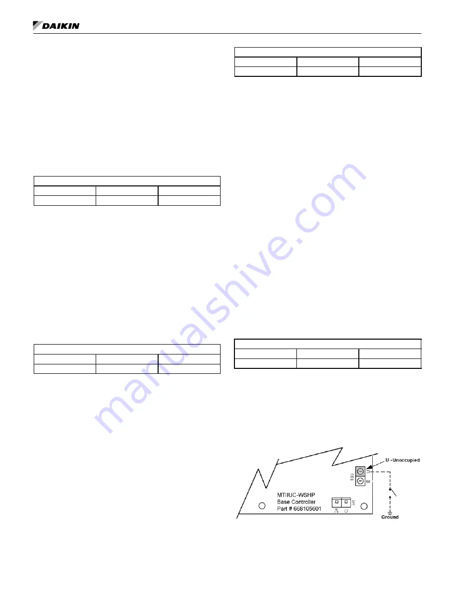
■
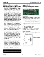
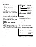
Unoccupied operation – stand alone thermostat
control
The board will be in unoccupied mode if the unoccupied
terminal (U) is grounded.
Board LED Status – Unoccupied
Yellow
Green
Red
On
On
Off
•
Thermostat inputs (G, Y1, Y2, W1, and
W2)
– The only thermostat inputs used during
unoccupied operation are Y2 and W2, which when
energized will activate Cooling Mode or Heating
Mode respectively. Inputs G, Y1 and W1 have no
effect during unoccupied mode.
Figure 6: Terminal "U" - Grounded for Unoccupied
M
ICro
t
eCh
III u
nIt
C
ontroller


