


OM 1239
18 www.DaikinApplied.com
■
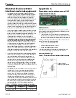
Tenant override button reset
•
The MicroTech III unit controller enters tenant
override mode when the Tenant Override (TO)
terminal is grounded for 4-10 seconds during
a period when the Water Source Heat Pump is
in unoccupied mode. Tenant override allows a
tenant, returning to the controlled space after
the unit has been placed in unoccupied mode, to
activate the tenant override input and place the
unit into occupied mode. Any remote button or
switch with momentary dry contacts can be used
for this purpose. During the 2-hour tenant override
period all the thermostat inputs will be used, (see
Occupied mode on page
12
) for unit operation. If
the U terminal is still grounded after the 2-hour time
limit, the unit will return to unoccupied mode. Refer
to "Unoccupied operation – stand alone thermostat
control" on page
15
.
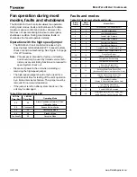
Heating mode
The W1 terminal controls the Stage 1 Heating Mode
of operation. When the W1 terminal is energized, the
following occurs:
1 .
The fan energizes.
2 .
The IV/PR (H8) control output de-energizes or
energizes depending on the H8 terminal wiring
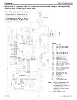
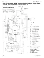
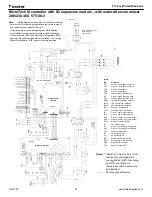
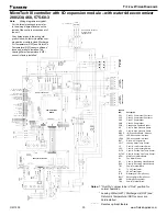
Refer to "MicroTech III unit controller and I/O
expansion module connector/terminal tables and
descriptions." on page
5
& "MicroTech III unit
controller terminal locations" on page
6
.
3 .
The lead compressor energizes after 45 seconds.
4 .
The reversing valve energizes 5 seconds after the
lead compressor turns on.
The W2 terminal controls the second stage of heating.
When the W2 terminal is energized, the following occurs:
1 .
The lag compressor is enabled when the interstage
timer has expired.
2 .
Five seconds later, the lag compressor reversing
valve is enabled.
When the W2 terminal is de-energized, the following
occurs:
1 .
The lag compressor is disabled.
When the W1 terminal is de-energized, the following occurs:
1 .
The lead compressor is de-energized.
2 .
The IV/PR (H8) control output energizes or de-
energizes depending on H8 terminal wiring. Refer
to "MicroTech III unit controller and I/O expansion
module connector/terminal tables and descriptions."
on page
5
& "MicroTech III unit controller
terminal locations" on page
6
.
3 .
The fan de-energizes, unless the G terminal is
energized.
Note:
To prevent compressor cycling, the required mini
-
mum on/off time default is 300 seconds. This may
cause the compressor time delay to be longer
than indicated above.
M
ICro
t
eCh
III u
nIt
C
ontroller


