


OM 1239
4
www.DaikinApplied.com
I
ntroduCtIon
Table 1: Control options
Control
Description
Application
Protocol
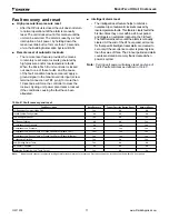
MicroTech III
(Standalone) Unit
Controller with I/O
Expansion Module
The MicroTech III controller is a
standalone microprocessor-based
control board conveniently located
in the unit control enclosure for easy
accessibility. The board is designed
to provide thermostat control of a
Water Source Heat Pump using a
two-stage wall thermostat. The unit
controller provides unit-wide control
of the WSHP and control of the first
refrigerant circuit.
Each unit controller is factory
programmed, wired, and tested for
complete control of single zone,
standalone operation of your Daikin
Water Source Heat Pump.
Unit-mounted or wall-mounted
thermostat or room sensor
The I/O Expansion Module is
an extension of the Microtech III
controller and provides control
of the second refrigerant circuit.
External LED status lights display
fault conditions to provide easy
troubleshooting and diagnosis of the
second circuit.
Allows for:
•
Control of second refrigeration
circuit.
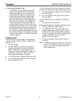
L
on
W
orks
Communication
Module
The MicroTech III control system
accepts a plug-in
L
on
W
orks
commu nication module to provide
network communications and
added functionality to easily
integrate with an existing BAS.
The communication module can
be factory- or field-installed and
is tested with all logic required to
monitor and control the unit.
L
on
T
aLk
application protocol
is designed for units that are
integrated into a
L
on
W
orks
communication network for
centralized scheduling and
management of multiple heat
pumps.
L
on
M
ark
3.4 Certified
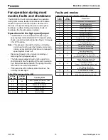
BACnet
Communication
Module
The MicroTech III controller
accepts a plug-in BACnet commu-
nication module to provide
network communications and
added functionality to easily
integrate with an existing BAS.
The communication module can
be factory- or field-installed and
is tested with all logic required to
monitor and control the unit.
Designed to be linked with a
centralized building automation
system (BAS) through a BACnet
communications network for
centralized scheduling and
management of multiple heat
pumps.
BACnet
MS/TP


