D
–EOMWC00A07-16_02EN
Operation Manual
16/77
6.4
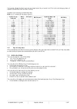
Extension I/O Fan Module Circuit #2
6.4.1
Digital Outputs
#
Description
Signal source
Output On
DO1
Circuit #2 Fan Step #1 Fan Off Fan On
Fan Off
Fan On
DO2
Circuit #2 Fan Step #2 Fan Off Fan On
Fan Off
Fan On
DO3
Circuit #2 Fan Step #3 Fan Off Fan On
Fan Off
Fan On
DO4
Circuit #2 Fan Step #4 Fan Off Fan On
Fan Off
Fan On
6.5
Extension I/O Fan Module Circuit #3
6.5.1
Digital Outputs
#
Description
Output Off
Output On
DO1
Circuit #3 Fan Step #1 Fan Off Fan On
Fan Off
Fan On
DO2
Circuit #3 Fan Step #2 Fan Off Fan On
Fan Off
Fan On
DO3
Circuit #3 Fan Step #3 Fan Off Fan On
Fan Off
Fan On
DO4
Circuit #3 Fan Step #4 Fan Off Fan On
Fan Off
Fan On
6.6
Extension I/O Unit Heat Pump (Old Version)
6.6.1
Digital Inputs
#
Description
Signal Off
Signal On
DI1
Cool Heat Switch
Cooling Mode
Heating Mode
DI2
Leak Detector
No Leak detected
Leak detected
6.7
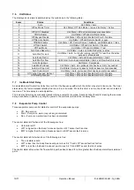
Extension I/O Unit Heat Pump (New Version)
6.7.1
Digital Outputs
#
Description
Output Off
Output On
DO1
Power Request (Marine option)
DO2
DO3
DO4
6.7.2
Analog Inputs
#
Description
Signal Source
Expected Range
AI1
Common Condenser Water Temperature
NTC Thermister 10K@25°C)
-50°C
– 120°C
6.7.3
Digital Inputs
#
Description
Signal Off
Signal On
AI 2
Mode Switch
Cooling Mode
Heating Mode
AI 3
Leak Detector
No Leak detected
Leak detected
AI 4
Power Available (Marine option)
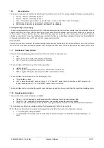
6.8
Setpoints
6.8.1
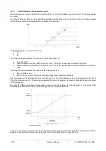
Auto Adjusted Ranges
Some settings have different ranges of adjustment based on the refrigerant type and operating mode.
Please refer to the product catalog for further information.

