ED 15103-6 • MICROTECH III WSHP UNIT CONTROLLER 24 www.DaikinApplied.com
C
omprehensIve
d
aTa
T
ables
l
on
W
orks
Network Variables
The following section contains relevant information needed to
integrate a MicroTech III WSHP into the
L
on
W
orks
network.
Refer to the appropriate data table based on the WSHP model.
The data point differences between the Enfinity Single Stage
Compressor and the SmartSource Two Stage Compressor/
Enfinity Large Two Compressor models are highlighted below
in the following tables.
CAUTION
Please note that anytime a command is written to a
configuration property input (nci), this information is stored
in the unit controller’s non-volatile memory. Writing to non-
volatile memory is an operation that has a finite limit. For this
reason, the number of writes made to configuration properties
must be limited in order to avoid damage to the hardware.
Enfinity Single Stage Compressor
Models: MHC/MHW, CCH/CCW, VFC/VFW, LVC/
LVW, and VHC/VHF models
•
: Network variable inputs (NVIs)
•
: Network variable outputs (NVOs)
•
: Configuration properties (NCIs)
SmartSource Single and Two Stage and
Enfinity Large Two Compressor
SmartSource Models: GSH/GSV, GTH/GTV, GCV
Enfinity Models: CCH/CCW and LVC/LVW
•
: Network variable inputs (NVIs)
•
: Network variable outputs (NVOs)
•
: Configuration properties (NCIs)
Refer to the
Selected Parameters Information
section that
follows these tables for the
L
on
W
orks
parameters that
require additional explanation. Also see
Space Temperature Setpoint Methods
Refer to the OM 1085 Software Downloading Procedures and
Troubleshooting Guide, available on
for software part number and compatibility details.
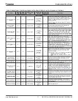
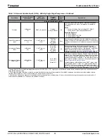
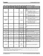
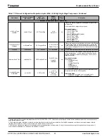
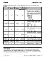
Table 15:
Network Variable Inputs (NVIs) - Enfinity Single Stage Compressor
Point Name
l
on
W
orks
Variable
(NV Index
2
)
SNVT Type
(SNVT Index)
Range/
Default
(in Units)
Heart-
beat
Description
Network Variable Inputs (NVIs)
Application Mode
Input
nviApplicMode
(4)
SNVT_hvac_mode
(108)
Default:
HVAC_NUL
Recv
Sets the unit in an application mode (Auto, Off, Heat, Cool,
Dehumidification, or Fan Only). Application Mode does not
“force” the unit into any state. However, it does disable
certain unit operations. Examples: 1) Application Mode
of Cool disables heating, 2) Heat disables cooling and
dehumidification, and 3) Fan Only disables heating, cooling,
and dehumidification.
3
PnviApplicMode overrides the local
room sensor’s System Mode Switch (Heat/Cool/Auto). The
local System Mode Switch is only used when nviApplicMode is
set to HVAC_NUL.
The network override will revert back to its default value upon
unit controller reboot.
Supported Values
0 = HVAC_AUTO
1 = HVAC_HEAT
3 = HVAC_COOL
6 = HVAC_OFF
9 = HVAC_FAN_ONLY
14 = HVAC_DEHUMID
-1 (0xFF) = HVAC_NUL
Auxiliary Heat Enable
Input
nviAuxHeatEnable
(5)
SNVT_switch
(95)
Default: Null
Recv
Enables or disables auxiliary heat units with electric heat.
Electric heat is always enabled when it is the only source of
heating, and is unaffected by this variable. The default state is
Null, in which case auxiliary heat is enabled.
3
The network override will revert back to its default value upon
unit controller reboot.
Selection State Value
Disabled 0 NA
Disabled 1 0%
Enabled 1 0.5 to 100%
Null -1 0%
1. Analog Null (0x7FFF) is a discrete temperature value of 621.806ºF/327.67ºC. Its purpose is to indicate a sensor failure condition or when the unit controller is not
using that temperature value.
2. The Network Variable (NV) index number is a unique identifier for certain
L
on
W
orks
variables. Some BAS companies use this numeric value instead of text to
reference these variables. The NV index number can also be found in the XIF file.
3. After Receive Heartbeat is enabled, this variable reverts to the default (non-override) value if it is not refreshed often enough through a network command or if
communication is disabled (i.e. the device is disabled or is offline).


