D
–EOMWC00A07-16_02EN
Operation Manual
14/77
6
CONTROLLER OPERATION
6.1
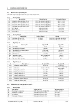
MicroTech Inputs/Outputs
The chiller may be equipped with one up to three compressors.
6.1.1
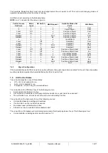
Analog Inputs
#
Description
Signal Source
Expected Range
AI1
Evaporator Entering Water Temp
NTC Thermister (10K@25°C)
-50°C
– 120°C
AI2
Evaporator Leaving Water Temp
NTC Thermister (10K@25°C)
-50°C
– 120°C
AI3
Condenser Entering Water Temp
NTC Thermister (10K@25°C)
-50°C
– 120°C
X1
Condenser Leaving Water Temp
NTC Thermister (10K@25°C)
-50°C
– 120°C
X4
LWT Reset
4-20 mA Current
1 to 23 mA
X7
Demand Limit
4-20 mA Current
1 to 23 mA
X8
Unit Current
4-20 mA Current
1 to 23 mA
6.1.2
Analog Outputs
#
Description
Output Signal
Range
X5
Condenser Pump VFD
0-10VDC
0 to 100% (1000 steps resolution)
X6
Condenser Bypass Valve
0-10VDC
0 to 100% (1000 steps resolution)
6.1.3
Digital Inputs
#
Description
Signal Off
Signal On
DI1
Unit PVM
Fault
No Fault
DI2
Evaporator Flow Switch
No Flow
Flow
DI3
Double Set Point/ Mode Switch
Cool mode
Ice mode
DI4
External Alarm
Remote off
Remote on
DI5
Unit Switch
Unit off
Unit on
DI6
Emergency Stop
Unit off/rapid stop
Unit on
X2
Current Limit Enable
Disabled
Enabled
X3
Condenser Flow Switch
No Flow
Flow
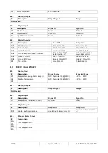
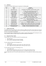
6.1.4
Digital Outputs
#
Description
Output OFF
Output ON
DO1
Evaporator Water Pump #1
Pump Off
Pump On
DO2
Unit Alarm
Alarm not Active
Alarm Active (Flashing=
circuit alarm)
DO3
Cooling Tower Out 1
Fan Off
Fan On
DO4
Cooling Tower Out 2
Fan Off
Fan On
DO5
Cooling Tower Out 3
Fan Off
Fan On
DO6
Cooling Tower Out 4
Fan Off
Fan On
DO7
DO8
Evaporator Water Pump #2
Pump Off
Pump On
DO9
Condenser Water Pump
Pump Off
Pump On
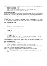
6.2
Extension I/O Compressor #1 to #3
6.2.1
Analog Inputs
#
Description
Signal Source
Expected Range
X1
Discharge Temperature
NTC Thermister (10K@25°C)
-50°C
– 120°C
X2
Evaporator Pressure
Ratiometric (0,5-4,5 Vdc)
0 to 5 Vdc
X3
Oil Pressure
Ratiometric (0,5-4,5 Vdc)
0 to 5 Vdc
X4
Condenser Pressure
Ratiometric (0,5-4,5 Vdc)
0 to 5 Vdc


