background image

40

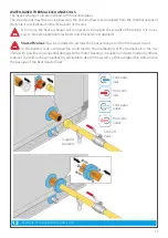
Shut-off 
valve

DIRECT EXPANSION THERMAL EXCHANGE COILS

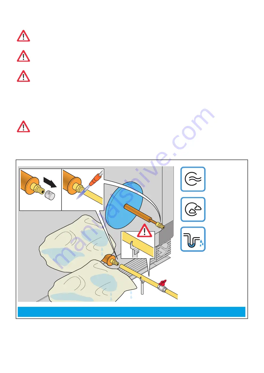
The filling by the installer must be performed according to current regulations and by authorised 

personnel, authorised for the use and handling of coolants.
The heat exchange coils are installed with horizontal pipes.
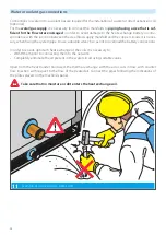
Do not use the heat exchange coil connections to support the weight of the piping. It is neces-
sary to prepare appropriate fasteners and brackets (not supplied).

Shut-off valves

 must be included to exclude the heat exchange coil from the coolant circuit.

The system piping must be connected to the heat exchange battery with braze welding, circulating 

an-

hydrous nitrogen

 inside the pipes to prevent oxides from forming. The liquid suction pipes must be the 

appropriate size for the expected potential and to ensure the circulation of the oil present in the coolant 
even when the heat exchange coil operates at minimum load. 

Use of wet patches to protect the plastic against the heat of the flame.

Condensate 
drain

Coolant 
inlet

Vapour outlet

13

Example of connection to gas coils

Summary of Contents for Modular Rotary

Page 1: ...Modular P and R Translation of the original instructions Installation use and maintenance manual Modular Rotary Modular Plate AHMN ADT DAIKIN EN...

Page 2: ...lable Armed with an extremely flexible development Daikin air handling units are able to satisfy all types of technical requirements Daikin systems guarantee respect for the environment since they are...

Page 3: ...13 Adhesives on the machine 14 Machine description 16 Receipt of the cartons 19 Reading the packaging symbols 19 Transport 20 Lifting using hooks 20 Lifting using a pallet truck 21 Lifting non pallet...

Page 4: ...tions for transport handling installation and assembly Use Information for instructing personnel authorised for its use Maintenance activities All information refers in general to any unit of the Modu...

Page 5: ...ED to work on mechanical systems Skills required for the installation of the machine Installers must perform operations according to their professional qualifications all activities not within one s e...

Page 6: ...he static and dynamic stability relative to the installation and to arrange environments so that people who are not competent or author ised DO NOT have access to the machine or to its commands It is...

Page 7: ...main calm and lucid quickly examine the situation and act accordingly if necessary disconnect the machine s power supply promptly call emergency services 118 in Italy without abandoning the victim exp...

Page 8: ...by the operator until the end of the clean ing operations Internal cleaning of the machine must be carried out using the protections required by current regulations While the inside of the machine do...

Page 9: ...ir proper status as soon as possible Key lock standard the doors to access the machine s fan area have a key lock on the handle to avoid their opening by unau thorised persons Micro Switch optional th...

Page 10: ...and constructive solutions transform environment friendliness and energy sav ings into valid and advanced technological solutions Environmental contamination Depending on the installation operating e...

Page 11: ...nstalled to inspect the inside of the machine Construction specifications Profile type anodised aluminium with thermal break Insulation panels polyurethane or mineral wool Base module Condensing or ab...

Page 12: ...gle or combined silencing module Combined silencing module with damper Electric pre or post heating module Humidification module Attachments To complete this manual together with the delivery of the m...

Page 13: ...Filter Filter Machine control system Heat recuperator Supply fan motor assembly Machine control system RECOVERY AIR EXTERNAL SUPPLY AIR INTERIOR EXTERNAL AIR EXHAUST AIR Filter Damper Filter Damper H...

Page 14: ...supply left Fans External air left Damper Exhaust air right Extracted air right Cold water inlet Cold water outlet Hot water inlet Hot water outlet Filter Extracted air left Electric coil Heat recuper...

Page 15: ...15 Notes...

Page 16: ...circuit during replacement Frame with supporting structure The frame is made of extruded profiles in anodised alumini um with a thermal break having a 40x40 mm cross section Coupling is done with nyl...

Page 17: ...rethane density of 45 Kg m3 and fire reaction Class 1 or mineral wool density of 120 Kg m3 and fire reaction Class 0 The material of the external sheet can be customised ac cording to the need for res...

Page 18: ...d contaminants into the circuit during replacement Frame with supporting structure The frame is made of extruded profiles in anodised alumini um with a thermal break having a 40x40 mm cross section Co...

Page 19: ...osion ranging from Aluzinc to pre painted sheet metal The panels are attached with stainless self drilling screws housed in nylon bushes the latter are embedded in the pan el and include a closing cap...

Page 20: ...he battery is controlled In the case of DX units are supplied with ERQ Daikin control board and Daikin electronic expansion valve mounted and connected In the case of water batteries the control is en...

Page 21: ...er and the carrier that made the delivery B There is NO visible damage move the machine to the site of installation Read the packaging symbols Externally the packaging bears all the information necess...

Page 22: ...ng the way e g electric cables beams etc When the loads are lifted the range of action of the lifting equipment must remain free of persons Use perfectly serviceable hooks chains or steel cables of ad...

Page 23: ...23 OK 15 15 15 15 Lifting with bracket hook up to Size 07 with aluminium base Lifting with ropes Lifting with eyebolts OK...

Page 24: ...the lifting tubes must be closed me chanically to prevent them from coming out of the holes provided Position the lifting ropes as shown in the figure in the part of the tube nearest the equipment Lif...

Page 25: ...014 http www daikinapplied eu Remove IMMEDIATELY the films at receiving the machine After unpacking check the integrity of the machine and any additional modules In case of damaged or missing parts Do...

Page 26: ...Mineral wool pre painted panel R Polyurethane aluzinc panel S Mineral wool aluzinc panel W Water D Direct expansion N No heat exchange coil or only electric coils for thermal and gas exchange V direc...

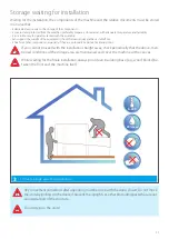
Page 27: ...mponents especially if they are potentially explosive incendiary toxic If you cannot proceed with the installation straight away check periodically that the above men tioned conditions of the storage...

Page 28: ...28 Notes...

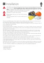
Page 29: ...nce with the Manufacturer s Technical Office The machine does not require special environmental conditions for its operation For a correct instal lation it is sufficient to prepare a level support sur...

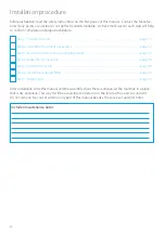
Page 30: ...cessary page 32 Step 3 Fasten the units to the ground optional page 35 Step 4 Make the connections page 36 Step 5 Perform a trial run page 48 Step 6 Install the required filters page 49 Step 7 Safety...

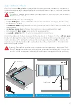
Page 31: ...r or gas A drain pipe with drain siphon connected to the sewerage system an aeraulic system ducts for the air to be conveyed to the environments Position the unit above the base Make sure that the are...

Page 32: ...e machine on the whole perimeter of contact just on one side Fasten all the coupling screws provided with the machine and then level the modules Tighten all the coupling screws entering into the units...

Page 33: ...33 VDI 6022 6...

Page 34: ...34 1 x TE8x35 1 x 8 5 1 x M8 2 x TE8x35 2 x 8 5 2 x M8 7...

Page 35: ...the ground tools and fastening components not included The installer is re sponsible for choosing the most suitable means of fastening based on experience the drawing includes an example There is no...

Page 36: ...ualified personnel after cutting off the facility s power supply Performed in a fixed and permanent manner without intermediate splices in accordance with the regulations of the country of installatio...

Page 37: ...Once the system has been set up the machine can be connected to the electricity supply network The actual supply voltage of the user devices must not deviate more than 10 from the expected normal vol...

Page 38: ...s sary when fixing the system pipe to use a double wrench so as not to overload the battery connections In order to ensure optimum heat exchange of the coils it is necessary to WASH them prior to conn...

Page 39: ...ackets not supplied Shut off valves must be included to exclude the heat exchange coil from the water circuit In the heating coils a stopped fan could lead to the overheating of the stagnant air in th...

Page 40: ...supplied Shut off valves must be included to exclude the heat exchange coil from the coolant circuit The system piping must be connected to the heat exchange battery with braze welding circulating an...

Page 41: ...imum siphon level Siphon minimum height 100 mm drain valve AIR GAP min 25 mm x x 20 mm 2 15 Drain siphon To avoid overflows from the collection tank and consequent flooding of the machine as well as t...

Page 42: ...s necessary to Clean the joint surfaces between the duct and the machine coil Apply a gasket to the flange in order to prevent air infiltration Carefully tighten the connecting screws Use silicone on...

Page 43: ...43 3 4 5 x 1 100mm 100mm 250mm 250mm 250mm 10 100mm 5mm...

Page 44: ...44 6 7 NO OK...

Page 45: ...45 H2O SOAP 8...

Page 46: ...46 9...

Page 47: ...47 Notes...

Page 48: ...being drained Inspect the correct installation and adequate electrical connection of the energy recovery equip ment together with a mechanical and electrical check Insert an anti vibration coupling be...

Page 49: ...l of the gaskets Remove the filters from their packaging only when ready to install them to avoid getting them dirty and contaminating them Make sure that the inside of the filter is not contaminated...

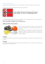
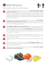
Page 50: ...s areas escape route etc PERSONAL PROTECTIVE EQUIPMENT Personal protective equipment should be used when operating the machine suitable for use in accordance with company crite ria and rules During ma...

Page 51: ...ers etc are correctly connected and powered Remove any foreign materials from inside the machine Check and keep the inside of the machine adequately clean Remove the blocks of the rotary recuperators...

Page 52: ...that the machine cannot be started Similarly press the emergency button on the outside of the control panel and check that the machine cannot be started Use of the machine It is essential that any dam...

Page 53: ...prohibited to remove any protections from moving parts and unit protection devices with the machine connected to the mains or operational Adjustments made with safe ty devices disengaged must be perfo...

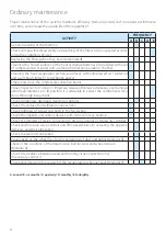
Page 54: ...basins Visual inspection for corrosion limescale release of fibrous substances any damage abnormal vibrations etc if possible it is advisable to extract the components for a more thorough inspection...

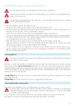
Page 55: ...onents or dampers use an industrial vacuum cleaner and or a com pressor Attention the compressed air flow must run opposite to the direction of the airflow through the unit and parallel to the fins Cl...

Page 56: ...parallel to the fins For the direct expansion system all the coolant in the batteries must be collected in the receiver before washing the coil with water This makes it possible to avoid the increase...

Page 57: ...General cleaning of the machine line Exchangers If there are dirt and dust deposits on the exchangers these can be easily removed using one of the fol lowing methods vacuum cleaner if there is not too...

Page 58: ...into detail as these are operations that fall within the abilities and professional expertise of the staff assigned to perform them Consumable components Spare parts During the operation of the machin...

Page 59: ...n Legislative Decree no 49 of 2014 Implementation of the WEEE Directive 2012 19 EU on electrical and elec tronic equipment waste The logo with the crossed out bin specifies that the product has been p...

Page 60: ...protection switch for the motor has been triggered or if its fuses have blown If this has occurred it may be caused by Motor overload due to mechanical problems They need to be solved Incorrect suppl...

Page 61: ...nals not installed Transducer failure with pressure control set point too high Machine Filters not inserted Access doors open Dampers not calibrated INSUFFICIENT THERMAL EFFICIENCY Heat exchange coil...

Page 62: ...62 Repair log DATE SERVICE TYPE TIME REQUIRED SIGNATURE...

Page 63: ...the values when pressed confirms the entered value lock main menu Green LED the unit is working properly Orange LED an alarm has been triggered opens the alarms screen brings up the previous page Refe...

Page 64: ...r implicit guarantee is given as to the completeness precision or reliability of its content All the data and specifications contained herein are subject to change without notice The data stated at th...

Reviews: