u
sIng
The
C
onTroller
www.DaikinApplied.com 45
IOM 1264-1 • NAVIGATOR
®
MODEL WWV CHILLERS
u
sIng
The
C
onTroller
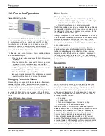
Unit Controller Operation
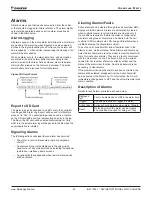
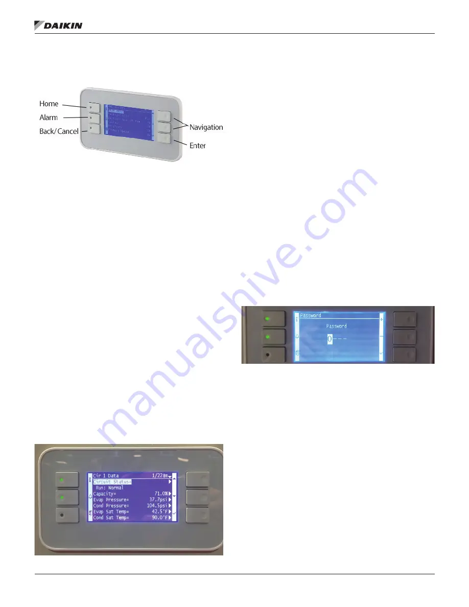
Figure 22: Unit Controller
The unit controller HMI/display is an 8-line display with 6
buttons (keys). The right side buttons are used for navigation
of the menus with up, down, and check/enter. The Up and
Down buttons move the cursor up and down the screen. If
the selected line links to another screen, there will be an
arrowhead on the right end of the line. To navigate to the linked
screen, the Enter button is pressed.
The three, left side buttons for Home, Alarm, and Back/Cancel
have LED indicator lights.
• When the Home button is pressed, the Main Menu screen
is displayed.
• When the Alarm button is pressed, the Alarm Log screen
is displayed. If there are active alarms and the alarm
button is pressed repeatedly, the HMI will cycle between
the Alarm Log screen, the Active Alarms screen, and the
Alarm Detail screen for the active alarm.
• When the Back button is pressed, the previously
displayed screen is displayed. This button can be pressed
repeatedly until the Main Menu screen is displayed.
Changing Parameter Values
When a setting or changeable field is selected on the screen,
the Enter button is pressed to enter edit mode. Once in edit
mode, the Up and Down buttons are used to adjust the value.
The Enter button is pressed to set the parameter to the
selected value. If the user wants to cancel any changes to the
parameter, the Back button can be pressed. When the Enter
or Back button are pressed, the interface returns to navigation
mode.
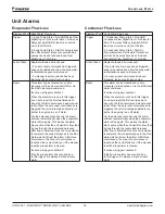
Figure 23: Example Menu Screen
Menu Details
Three types of lines exist:
•
Menu title, displayed in the first line as in
Figure 23
.
• Link (also called Jump) having an arrow ( > ) in the right
of the line and used to link to the next menu.
• Parameters with a value or adjustable set point.
The first line visible on each display includes the menu title and
the line number indicating which menu number you are on and
the total number of menus. In the above menu screen, the title
is Cir 1 Data and it is menu 1 of 22.
The right most position of the title line includes an “up” arrow ▲
to indicate there are menus (parameters) “above” the currently
displayed line; and/or a “down” arrow ▼ to indicate there
are menus “below” the currently displayed items or an “up/
down” arrow to indicate there are lines “above and below” the
currently displayed line.
Each line on a screen can contain status-only information
or include changeable data fields (set points) and becomes
highlighted when the cursor is on that line. A line in a menu
may also be a link to further menus. An arrow is displayed to
the far right of the line to indicate it is a “jump” line, meaning
pushing the bottom right checkmark button will cause a “jump”
to a new menu.
Passwords
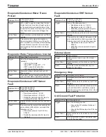
Figure 24: Password screen
When the HMI is first accessed or if the HMI has been idle
for longer than the Password Timeout (default 30 minutes),
the display will show a “startup” page where a password is
entered or continue without entering a password. Once a
valid password is entered or if continuing without a password,
the display changes to the Main Menu. There are 4 levels of
access for the user interface:
• No password
• Operator level - 5321
• Technician/Manager level - Provided at startup
• Daikin Applied service technician level
Read/write access to unit setpoints is dependent upon the
entered password level. Continuing without a password allows
access only to the Main Menu with read only capability to
basic status items. The Operator password allows access
to more status information as well as read/write access
to basic set points required to set up the unit for “normal”
operation. TheTechnician/Manager password allows similar
access to Operator with the addition of more advanced status
and commissioning set points. The Daikin Applied service
technician has the highest level of access.
Summary of Contents for Navigator WWV
Page 4: ......

