I
nsTallaTIon
and
a
pplICaTIon
C
onsIderaTIons
www.DaikinApplied.com
9
IOM 1264-1 • NAVIGATOR
®
MODEL WWV CHILLERS
Heat Exchanger Water Piping
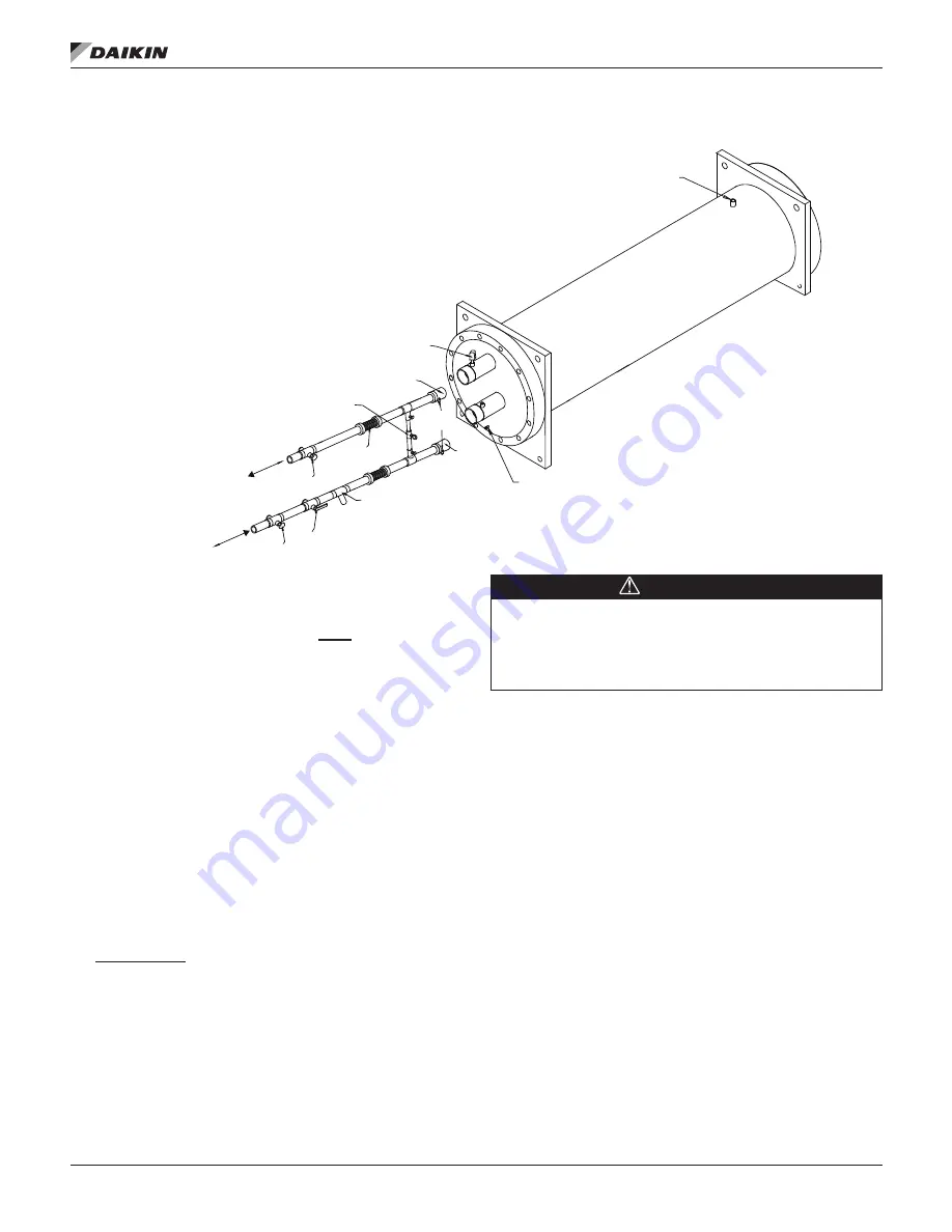
Figure 3: Typical Piping, Shell and Tube Evaporator
Be sure that water inlet and outlet connections match certified
drawings and nozzle markings.
Field installed water piping to the chiller
must
include:
• air vents at the high points.
• a cleanable water strainer upstream of the evaporator
and condenser inlet connections.
•
a flow proving device for both the evaporator and
condenser to prevent freeze up. Flow switches, thermal
dispersion switches, or Delta-P switches can be used.
Note that thermal dispersion flow switches are factory
installed as standard. Additional flow switches can be
used only if they are connected in series with the ones
already provided.
•
sufficient shutoff valves to allow vessel isolation. The
chiller must be capable of draining the water from the
evaporator or condenser without draining the complete system.
• matching mechanical connections. All evaporators and
condensers have OGS-type grooved water connections
(adhering to Standard AWWA C606) or optional flange
connections. PVC piping should not be used.
It is recommended
that field installed water piping to the chiller
include:
• temperature sensors at the inlet and outlet connections of
both vessels.
• water pressure gauge connection taps and gauges at the
inlet and outlet connections of both vessels for measuring
water pressure drop.
CAUTION
When common piping is used for both building heating and
cooling modes, care must be taken to provide that water
flowing through the evaporator cannot exceed 110°F. Water
this hot can damage controls or cause the relief valve to
discharge refrigerant.
Piping must be supported to eliminate weight and strain on
the fittings and connections. Chilled water piping must be
adequately insulated.
System Water Volume
All chilled water systems need adequate time to recognize a
load change, respond to that load change and stabilize, without
undesirable short cycling of the compressors or loss of control.
In air conditioning systems, the potential for short cycling
usually exists when the building load falls below the minimum
chiller plant capacity or on close-coupled systems with very
small water volumes. Some of the things the designer should
consider when looking at water volume are the minimum
cooling load, the minimum chiller plant capacity during the low
load period and the desired cycle time for the compressors.
A storage tank may have to be added to the system to reach
the recommended system volume. Refer to AG 31-003 for
method of calculating “Minimum Chilled Water Volume”.
The water quality provided by the owner/occupant/operator/
user to a chiller system should minimize corrosion, scale
buildup, erosion, and biological growth for optimum efficiency
of HVAC equipment without creating a hazard to operating
personnel or the environment. Strainers must be used to
protect the chiller systems from water-borne debris. Daikin will
RELIEF
3/8” PIPE PLUG
DRAIN
WELDED PIPE CONNECTIONS ARE NOT ALLOWED
BETWEEN THE STRAINER AND EVAPORATOR DUE TO THE
CHANCE OF SLAG ENTERING THE EVAPORATOR
FLOW
SWITCH
GATE
VALVE
FLOW
FLOW
OUTLET
BALANCING
VALVE
VIBRATION
ELIMINATORS
WATER
STRAINER
VALVED
PRESSURE
GAUGE
INLET
TEMP .
SENSOR
WELLS
GATE
VALVE
Note: ASME certification will be revoked if welding is performed on a vessel
shell or tube sheet.
Summary of Contents for Navigator WWV
Page 4: ......


