IOM 1242-8 • PATHFINDER
®
MODEL AWV CHILLERS
34 www.DaikinApplied.com
Installation and Application Considerations - Remote Evaporators
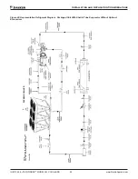
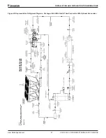
Piping Layout
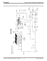
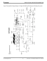
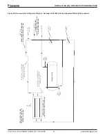
shows the piping layout for one of the two refrigerant
circuits for AWV units with a remote evaporator with and
without the optional economizer circuit. The outdoor unit, the
evaporator, and a kit of refrigerant components are shipped
as separate pieces for field mounting, wiring, and piping. The
suction shutoff valve is standard on remote evaporator units.
All components between the “Field Connection Points” should
be located as close to the evaporator as possible.
Note:
Field insulation of the suction lines and the liquid line on
circuits with economizers is required. The outdoor unit will have
a refrigerant charge equal to that of a packaged unit pumped
down into the condenser. Any additional charge of refrigerant
and oil required by the field piping is supplied by the customer.
The location and size of the refrigerant connections are shown
on dimensional drawings available from a Daikin Applied sales
representative.
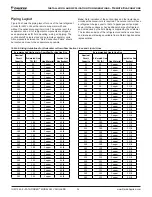
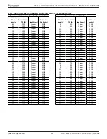
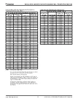
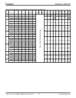
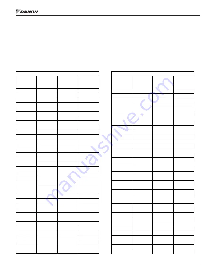
Table 6:
Sizing Guidelines for Horizontal or Downflow Suction Lines and Liquid Lines
Recommended Horizontal or Downflow Suction Line Size
Nominal
Circuit
Capacity
Estimated Line
TEL (ft)
Line Material
Suction Line
Size (Inches)
65
50
Copper
3 5/8
90
50
Copper
3 5/8
115
50
Copper
3 5/8
140
50
Copper
4 1/8
165
50
Copper
4 1/8
190
50
Copper
4 1/8
215
50
Copper
5 1/8
240
50
Copper
5 1/8
265
50
Copper
5 1/8
65
75
Copper
3 5/8
90
75
Copper
3 5/8
115
75
Copper
4 1/8
140
75
Copper
4 1/8
165
75
Copper
5 1/8
190
75
Copper
5 1/8
215
75
Copper
5 1/8
240
75
Copper
5 1/8
265
75
Copper
5 1/8
65
100
Copper
3 5/8
90
100
Copper
3 5/8
115
100
Copper
4 1/8
140
100
Copper
5 1/8
165
100
Copper
5 1/8
190
100
Copper
5 1/8
215
100
Copper
5 1/8
240
100
Copper
6 1/8
265
100
Copper
6 1/8
65
125
Copper
3 5/8
90
125
Copper
4 1/8
115
125
Copper
4 1/8
140
125
Copper
5 1/8
165
125
Copper
5 1/8
190
125
Copper
5 1/8
215
125
Copper
6 1/8
240
125
Copper
6 1/8
265
125
Copper
6 1/8
Recommended Liquid Line Size
Nominal
Circuit
Capacity
Estimated Line
TEL (ft)
Line Material
Liquid Line Size
(Inches)
65
50
Copper
1 5/8
90
50
Copper
1 5/8
115
50
Copper
1 5/8
140
50
Copper
1 5/8
165
50
Copper
2 1/8
190
50
Copper
2 1/8
215
50
Copper
2 1/8
240
50
Copper
2 1/8
265
50
Copper
2 1/8
65
75
Copper
1 5/8
90
75
Copper
1 5/8
115
75
Copper
2 1/8
140
75
Copper
2 1/8
165
75
Copper
2 1/8
190
75
Copper
2 1/8
215
75
Copper
2 1/8
240
75
Copper
2 1/8
265
75
Copper
2 5/8
65
100
Copper
1 5/8
90
100
Copper
1 5/8
115
100
Copper
2 1/8
140
100
Copper
2 1/8
165
100
Copper
2 1/8
190
100
Copper
2 1/8
215
100
Copper
2 5/8
240
100
Copper
2 5/8
265
100
Copper
2 5/8
65
125
Copper
1 5/8
90
125
Copper
1 5/8
115
125
Copper
2 1/8
140
125
Copper
2 1/8
165
125
Copper
2 1/8
190
125
Copper
2 5/8
215
125
Copper
2 5/8
240
125
Copper
2 5/8
265
125
Copper
2 5/8

