Circuit Functions
www.DaikinApplied.com 67
IOM 1242-8 • PATHFINDER
®
MODEL AWV CHILLERS
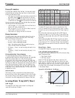
Circuit 2
# Fans
4
6
8
10
12
14
16
Fan
Output
#
1
201
201
201
201
201
201
-
2
202
202
202
202
202
202
-
3
203
203
203
203,205
203,205
203,205
-
4
204
204,206
204
204,206
204,206
204,206
-
5
-
205
105,107
207,209 207,209,211
207,209,211,213
-
6
-
-
106,108
208,210 208,210,212 208,210,212,214
-
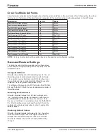
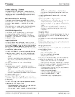
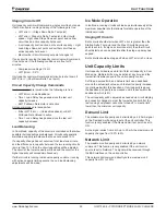
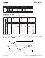
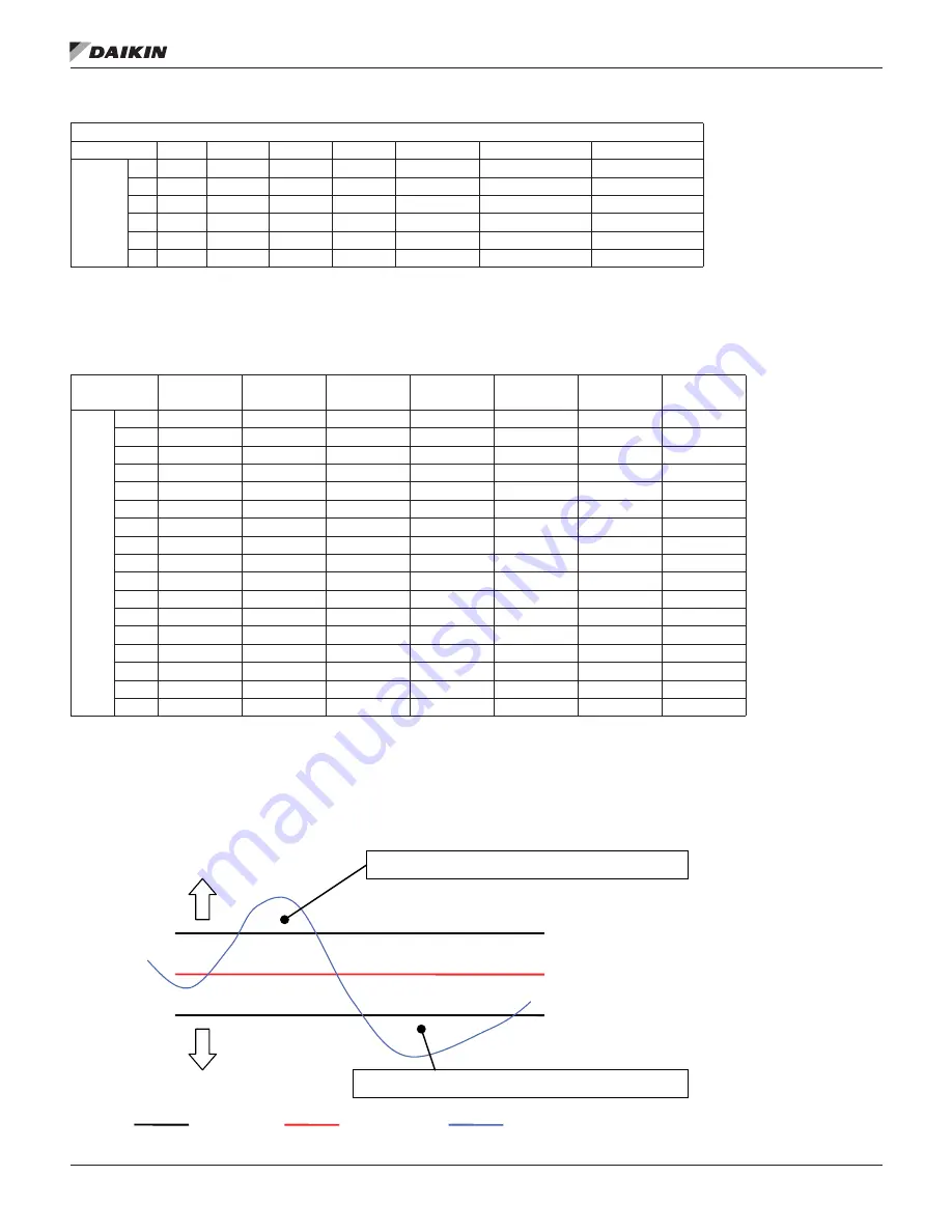
Fan Outputs Per Fan Stage
The table below shows which digital outputs are energized for each stage.
Table 58: Digital Outputs Energized for Each Stage
# Fans On
Circuit
4
6
8
10
12
14
16
Fan
Stage
0
0
0
0
0
0
0
0
1
1
1
1
1
1
1
1
2
1,3
1,3
1,3
1,2
1,2
1,2
1,2
3
1,2,3
1,3,5
1,5
1,3
1,3
1,3
1,3
4
1,2,3,4
1,2,3,5
1,3,5
1,2,3
1,5
1,2,3
1,2,3
5
-
1,3,4,5
1,2,3,5
1,3,5
1,2,5
1,5
1,5
6
-
1,2,3,4,5
1,2,3,4,5
1,2,3,5
1,3,5
1,2,5
1,2,5
7
-
-
1,2,3,5,6
1,3,4,5
1,2,3,5
1,3,5
1,3,5
8
-
-
1,2,3,4,5,6
1,2,3,4,5
1,3,4,5
1,2,3,5
1,2,3,5
9
-
-
-
1,3,4,5,6
1,2,3,4,5
1,3,4,5
1,4,5
10
-
-
-
1,2,3,4,5,6
1,2,3,5,6
1,2,3,4,5
1,2,4,5
11
-
-
-
-
1,3,4,5,6
1,3,5,6
1,3,4,5
12
-
-
-
-
1,2,3,4,5,6
1,2,3,5,6
1,2,3,4,5
13
-
-
-
-
-
1,3,4,5,6
1,4,5,6
14
-
-
-
-
-
1,2,3,4,5,6
1,2,4,5,6
15
-
-
-
-
-
-
1,3,4,5,6
16
-
-
-
-
-
-
1,2,3,4,5,6
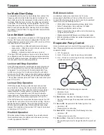
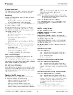
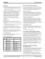
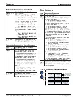
Staging Concept
As long as the condenser saturated temperature is within the band defined by the active stage up deadband and active stage down
deadband, the fan stage will not change. When saturated condenser temperature is outside of the deadbands, error is accumulated
and will cause a change in the fan stage.
Figure 72: Fan Staging Conditions
If this error accumula
ti
on is greater than 3.0°C Fan stage down.
If this error accumula
ti
on is greater than 11°C, Fan stage up.
(Target) + (stage up deadband)
Saturated Condenser
Temperature Target
(Target) - (stage down deadband)
Limit
Error
Error
Target
Condenser saturated temperature

