IOM 1242-8 • PATHFINDER
®
MODEL AWV CHILLERS
72 www.DaikinApplied.com
Alarms and Events
Alarms and Events
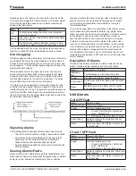
Situations may arise that require some action from the chiller,
or that should be logged for future reference. The alarm digital
output will be operated based on active alarm scenarios as
shown in the table below.
State
Scenario
Off
No alarms preventing the chiller or an individual
circuit from running
Blinking One, and only one, circuit has an alarm preventing
it from running
On
Unit alarm preventing chiller from running or both
circuits have alarms preventing them from running
For the Blinking state, the output should cycle five seconds on
then five seconds off while the indicated scenario is active.
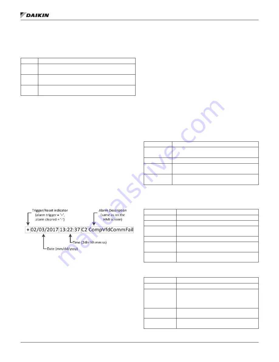
Alarm Logging
All alarms appear in the active alarm list while active. All alarms
are added to the alarm log when triggered and when cleared.
Entries in the log representing the occurrence of an alarm will
be preceded by ‘+’ while entries representing the clearing of an
alarm will be preceded by ‘-’.
When an alarm occurs, the alarm type, date, and time are
stored in the active alarm buffer corresponding to that alarm
(viewed on the Alarm Active screens), and also in the alarm
history buffer (viewed on the Alarm Log screens). The active
alarm buffers hold a record of all current alarms.
The alarm log can be exported to a formatted SD card in the
controller. A setting called “Alarm Log Export” will be used to
initiate this when set to Yes. The exported log will be saved in a
text file on the SD card with each line representing an entry in
the log. Only what is in the actual alarm log will be saved to the
file when the export was initiated.
Signaling Alarms
The following actions will signal that an alarm has occurred:
•
The unit or circuit executes a rapid or pumpdown shutoff.
• An alarm bell icon will be displayed in the upper right-
hand corner of all controller screens, including the
optional remote user interface panel’s screens.
•
An optional field supplied and wired remote alarm device
will be activated.
Clearing Alarms/Faults
Active alarms can be cleared through the keypad/display or a
BAS network. Alarms are automatically cleared when controller
power is cycled. Alarms are cleared only if the conditions
required to initiate the alarm no longer exist. All alarms and
groups of alarms can be cleared via the keypad or network
via LON using nviClearAlarms and via BACnet using the
ClearAlarms object.
To use the keypad, follow the Alarm links to the Alarms screen,
which will show Active Alarms and Alarm Log. Select Active
Alarm and press the wheel to view the Alarm List (list of current
active alarms). They are in order with the most recent on
top. The second line on the screen shows Alm Cnt (number
of alarms currently active) and the status of the alarm clear
function. An active password is not necessary to clear alarms.
If the problem(s) causing the alarm have been corrected, the
alarms will be cleared, disappear from the Active Alarm list
and be posted in the Alarm Log. If not corrected, the On will
immediately change back to OFF and the unit will remain in the
alarm condition.
Description of Alarms
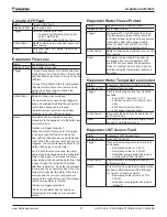
Details for each alarm are listed in a table format as shown
below. The table below explains each row in the tables.
Alarm:
Description of the alarm
Displayed
Text:
Text displayed on HMI in the alarm lists
Trigger:
Conditions required to trigger the alarm
Action Taken: Actions that should be taken when the alarm
triggers
Reset:
Method by which the alarm can be cleared
and conditions required for doing so, if any
Unit Alarms
Unit GFP Fault
Alarm:
Unit GFP Fault
Displayed Text: Unit Ground Fault
Trigger:
All of the following are true:
• Ground Fault Protection Option set
point = Single Point
•
GFP Relay 1 input is off for 1 second
Action Taken:
Rapid shutdown all circuits and lock out
unit from running
Reset:
Auto reset when GFP Relay 1 input is on
for 5 seconds
Circuit 1 GFP Fault
Alarm:
Circuit 1 GFP Fault
Displayed Text: C1 Ground Fault
Trigger:
All of the following are true:
• Ground Fault Protection Option set
point = Multi Point
•
GFP Relay 1 input is off for 1 sec
Action Taken:
Rapid shutdown all circuits and lockout unit
from running.
Reset:
Auto reset when GFP Relay 1 input is on
for 5 seconds

