Alarms and Events
www.DaikinApplied.com 75
IOM 1242-8 • PATHFINDER
®
MODEL AWV CHILLERS
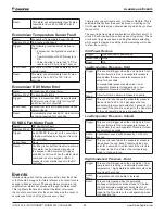
Evaporator Pump #1 Failure
Alarm:
Evaporator Pump #1 Failure
Displayed Text: Evap Pump 1 Fault
Trigger:
Unit is configured with primary and backup
pumps, pump #1 is running, and the pump
control logic switches to pump #2.
Action Taken:
Backup pump is used
Reset:
This alarm can be cleared manually via the
keypad or BAS command.
Evaporator Pump #2 Failure
Alarm:
Evaporator Pump #2 Failure
Displayed Text: Evap Pump 2 Fault
Trigger:
Unit is configured with primary and backup
pumps, pump #2 is running, and the pump
control logic switches to pump #1.
Action Taken:
Backup pump is used
Reset:
This alarm can be cleared manually via the
keypad or BAS command.
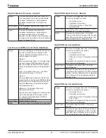
Bad Demand Limit Input
Alarm:
Bad Demand Limit Input
Displayed Text: Bad Demand Lim Input
Trigger:
Demand limit input out of range and
Demand Limit set point is set to On. For
this alarm, out of range is considered to be
a signal less than 3 mA or more than 21
mA.
Action Taken:
Demand limit function and signal are
ignored
Reset:
Auto clear when Demand Limit set point
is set to Off or demand limit input back in
range for 5 seconds.
Bad LWT Reset Input
Alarm:
Bad LWT Reset Input
Displayed Text: Bad LWT Reset Input
Trigger:
LWT Reset Type set point is 4-20 mA and
LWT reset input out of range. For this alarm
out of range is considered to be a signal
less than 3 mA or more than 21 mA.
Action Taken:
LWT reset signal and 4-20 mA function are
ignored
Reset:
Auto clear when LWT Reset Type set point
is not 4-20 mA or LWT reset input back in
range for five seconds.
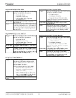
Economizer EXV Module Comm Failure
Alarm:
Economizer EXV Module Comm Failure
Displayed Text: EconExvModCommFail
Trigger:
Economizer Configuration set point is set to
Yes and communication with the economizer
EXV module has failed. Specifically, this
means that 16 consecutive failures of read/
write command blocks for this address have
occurred.
Action Taken:
Economizer valve command is set to
0% in control logic, though without
communication the module is left to operate
per logic embedded in it. It should be set
up to automatically close the valves when
communication is lost.
Reset:
This alarm can be cleared manually
via the keypad or BAS command after
communication is restored for at least 5
seconds.
RapidRestore Module Comm Failure
Alarm:
RapidRestore Module Comm Failure
Displayed Text: RR Module Comm Fail
Trigger:
RapidRestore set point is set to ‘Yes’ and
communication with the RapidRestore
module has failed. This means the reliability
value reported for the module is anything
other than 0 for at least 3 seconds.
Action Taken:
RapidRestore functionality will be disabled
while the module is not communicating since
an input on the module is required in order
to enable the functionality.
Reset:
This alarm will automatically clear after
communication is restored for at least 5
seconds.
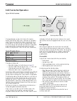
Waterside Economizer EWT Sensor
Fault
Alarm:
Waterside Economizer EWT Sensor Fault
Displayed Text: WSE EWT SenFault
Trigger:
If any of the following occur for more than
one second:
•
Resistance value is < 340 Ω
•
Resistance value is > 300 kΩ
• Reliability value reported for input is
anything other than ‘NoFault’
Action Taken:
Cannot use Waterside economizer
Reset:
This alarm can be cleared manually via the
keypad or BAS command if the following
are true for at least 5 seconds:
•
Resistance value is from 340 Ω to
300 kΩ
• Reliability value reported for input is
‘NoFault’

