IOM 1242-8 • PATHFINDER
®
MODEL AWV CHILLERS
62 www.DaikinApplied.com
Circuit Functions
Circuit Functions
Circuit Functions
Components controlled at the circuit level include:
• Compressor VFD
• Compressor VR Solenoid Valves
• Evaporator EXV
• Economizer EXV
• Liquid Line Solenoid Valve
• Liquid Injection Solenoid Valve
• Condenser Fans
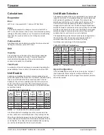
Calculations
Calculations are for each circuit.
Approach Values
Evaporator Approach = LWT – Evap Saturated Temp
Condenser Approach = Cond Saturated Temp – OAT
Superheat Values
Suction superheat = Suction Temp – Evap Saturated Temp
Discharge superheat = Discharge Temp – Cond Saturated
Temp
Economizer Superheat = Econ Temp – Econ Saturated Temp
Differential Pressure Values
Oil Pressure Differential = Cond Pressure - Oil Pressure
Pressure Difference = Cond Pressure – Evap Pressure
Pressure Ratio
Pressure Ratio = (Cond Press +101.325) ÷ (Evap Press +
101.325)
Feedback Capacity
Feedback capacity is a representation of the actual capacity as
a percentage of full capacity based on feedback regarding the
actual speed of the compressor.
Compressors vary capacity via changes to the speed. The
actual compressor speed is read from the VFD. Feedback
capacity for a compressor with a VFD is:
Actual Compressor Speed x 100 ÷ Maximum Speed
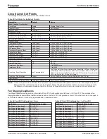
Saturated Condenser Temperature Limit
The maximum saturated condenser temperature calculation
is based on the compressor operational envelope. This value
is used for triggering high condenser pressure alarms and as
a reference for the trigger values of the high pressure hold
and unload events. Chiller software is designed to calculate
a dynamic maximum saturated condenser temperature.
High saturated condenser hold and unload offset values are
described as follows.
Table 52: Saturated Condenser Temperature Conditions
Condition
Saturated Evap
Temp or LWT
Max Cond Saturated
Temp (°C)
EXV state is Start
Pressure Control
LWT
≤ 0
°C
1.589 X LWT + 68.3
LWT > 0°C
68.3
EXV state is SSH
or MOP Control
Te
≤ 0
°C
1.589 X Te + 68.3
Te > 0°C
68.3
All other conditions
n/a
68.3
High Saturated Condenser – Hold Value
High Cond Hold Value = Max Saturated Cond Value – High
Cond Press Hold Offset set point
High Saturated Condenser – Unload Value
High Cond Unload Value = Max Saturated Cond Value – High
Cond Press Unload Offset set point
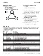
Maximum Compressor VFD Output
Current
Max Motor Current = Minimum of (VFD Rated Current, Motor
Rated Current)
where:
- VFD Rated Current is read from the compressor VFD
- Motor Rated Current is determined by the compressor type
and the voltage configuration:
Motor Rated Current (Amps)
Compressor
Type
380V
400V
460V
575V
F3ALVVR60
222.8
222.8
183.3
167.0
F3ALVVR86
375.6
375.6
311
253.5
F3BLVVR86
527.9
527.9
434.1
N/A
F4ALVVR80
692.1
692.1
574.8
N/A
3120
175
175
175
175
3122
230
230
230
230
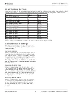
Pumpdown Target Value
The pressure target for pumpdown when the circuit enters the
pumpdown state is selected as follows:
If Service Pumpdown set point = Disable
Then Pumpdown Target = Evaporator Pressure at
pumpdown start – 20 kPa with value limited to the range
from 35 kPa to the Pumpdown Pressure Max set point
If Service Pumpdown set point = Enable
Then Pumpdown Target = 35 kPa

