background image

Si33-105

Test Operation

Test Operation R407C PLUS Series Heat Recovery System

123

1.10

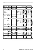
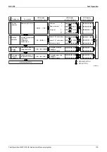
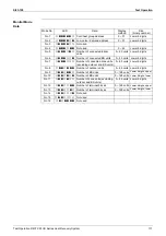
Refrigerant Recovery Mode

!

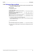
The electronic expansion valves in the indoor and outdoor units are fixed in the fully 
open position for refrigerant recovery.

[Work procedure]
1. Stop equipment operation.

2. Set the service mode.

3. Turn off the power switches of the indoor and outdoor units.

(Turn off the power switch for one of indoor or outdoor unit, then turn off the power switch of 
the other unit within 10 minutes.)

4. Conduct refrigerant recovery.

5.

!

Cancel the setting in the setting mode or cancel the mode by conducting power reset of the 
outdoor unit.

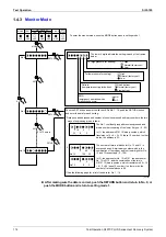
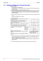
In service mode 1, press the “MODE” button for 5 seconds to 
enter service mode 2.

8  7  7  7  7  7  7

Press the “SET” button to set the LED indicators to the 
"refrigerant recovery mode" indication.

8  7  8  7  8  7  8

Press the “RETURN” button.

8  7  7  7  7  7  9

Press the “SET” button to set the LED indicators as shown at 
right.

8  7  7  7  7  9  7

Press the “RETURN” button to end the setting operation.

8  7  7  7  7  8  7

Press the “RETURN” button again to return to initial status.

8  7  7  7  7  7  7

Summary of Contents for R407C PLUS

Page 1: ...System R407C PLUS Series Heat Recovery System Si33 105 Service Manual ...

Page 2: ...ion and Combination 5 Part 2 Specifications R407C PLUS Series Heat Recovery System 7 1 Specifications 8 1 1 Outdoor Unit 8 1 2 BS unit 12 1 3 Indoor Unit 13 Part 3 Function R407C PLUS Series Heat Recovery System 31 1 Refrigerant System Diagram 32 1 1 Outdoor Unit Refrigerant System Diagram 32 1 2 BS unit Refrigerant System Diagram 37 1 3 Flow of Refrigerant in Each Operating Mode 39 2 List of Safe...

Page 3: ... 139 1 1 Indoor Unit Operation Flowchart 139 2 Troubleshooting by Remote Controller 144 2 1 The INSPECTION TEST Button 144 2 2 Self diagnosis by Wired Remote Controller 145 2 3 Self diagnosis by Wireless Remote Controller 146 2 4 Operation of The Remote Controller s Inspection Test Operation Button 150 2 5 Remote Controller Service Mode 151 2 6 Remote Controller Self Diagnosis Function 153 3 Troub...

Page 4: ...Transmission Between Master and Slave Remote Controllers 186 3 31 Malfunction of Transmission Between Indoor and Outdoor Units in the Same System 187 3 32 Excessive Number of Indoor Units 188 3 33 R22 R407C Indoor Unit mixed Connection 189 3 34 Address Duplication of Central Remote Controller 190 3 35 Refrigerant System not Set Incompatible Wiring Piping 191 3 36 Malfunction of System Refrigerant ...

Page 5: ...eration Lamp Blinks 214 8 2 Display Under Host Computer Integrate Control Blinks Repeats Single Blink 215 8 3 Display Under Host Computer Integrate Control Blinks Repeats Double Blink 217 Part 6 Appendix R407C PLUS Series Heat Recovery System 219 1 Piping Diagram 220 1 1 Outdoor Unit 220 1 2 BS Unit 222 1 3 Indoor Unit 224 2 Wiring Diagram 225 2 1 Outdoor Unit 225 2 2 BS Unit 227 2 3 Indoor Unit 2...

Page 6: ...lug socket before disassembling the equipment for a repair Working on the equipment that is connected to a power supply can cause an electrical shook If it is necessary to supply power to the equipment to conduct the repair or inspecting the circuits do not touch any electrically charged sections of the equipment If the refrigerant gas discharges during the repair work do not touch the discharging...

Page 7: ...he applicable model and appropriate tools to conduct repair work Never attempt to modify the equipment The use of inappropriate parts or tools can cause an electrical shock excessive heat generation or fire When relocating the equipment make sure that the new installation site has sufficient strength to withstand the weight of the equipment If the installation site does not have sufficient strengt...

Page 8: ...ce valve to prevent the refrigerant gas from leaking into the room The refrigerant gas itself is harmless but it can generate toxic gases when it contacts flames such as fan and other heaters stoves and ranges When replacing the coin battery in the remote controller be sure to disposed of the old battery to prevent children from swallowing it If a child swallows the coin battery see a doctor immed...

Page 9: ...al shock Be sure to measure the insulation resistance after the repair and make sure that the resistance is 1 Mohm or higher Faulty insulation can cause an electrical shock Be sure to check the drainage of the indoor unit after the repair Faulty drainage can cause the water to enter the room and wet the furniture and floor Icon Type of Information Description Note Note A note provides information ...

Page 10: ...air conditioning needs We are confident that customers will be able to find the models that best suit their needs This service manual contains information regarding the servicing of the R407C VRV PLUS series Heat Recovery System The following technical documents are also available from Daikin Please use these documents together with this manual to conduct efficient servicing Design Installation in...

Page 11: ...Introduction Si33 105 x ...

Page 12: ...General Information General Information R407C PLUS Series R407C PLUS Series R407C PLUS Series R407C PLUS Series Heat Recovery System Heat Recovery System Heat Recovery System Heat Recovery System 1 Product Outline 2 1 1 Year 2001 Models Using New Refrigerant 2 1 2 Outline of New Series Products 3 1 3 Model Configuration and Combination 5 ...

Page 13: ...YP16 20K Max 20 units RSEYP24 30K Max 32 units New model Equivalent horsepower HP Series name 16 18 20 24 26 28 30 R407C VRV PLUS series Heat Recovery System New model Model change Continued model Type P20 Type P25 Type P32 Type P40 Type P50 Type P63 Type P80 Type P100 Type P125 Type P200 Type P250 Ceiling mounted cassette type Multi flow type Double flow type Corner type Ceiling mounted built in ...

Page 14: ...n by function unit less structure Simpler piping work at installation sites Reduced unit installation area 13 7 20HP 11 6 30HP Feature 2 Reduction of installation area Simpler piping work at installation sites 20HP 30HP Pipe connecting locations 15 joints 7 joints 21 joints 7 joints Standard series General name Main unit name Sub unit name RSEYP KJY1 REYP KJY1 RXEP8 10KJY1 Main units Sub units V08...

Page 15: ... as 15 C Simple REFNET piping system Super wiring system Automatic address setting function Built in wiring error check function Equipped with sequential start function Nighttime low noise mode for reduced operating sound Long refrigerant piping equivalent length of 125 actual length of 100 m and height difference of 50 m Connection of indoor unit of varying capacities and types totaling 130 max o...

Page 16: ...225 585 250 650 300 780 Standard series Equivalent output 26HP 28HP 30HP R407C VRV PLUS series system model RSEYP26KJ RSEYP28KJ RSEYP30KJ Outdoor unit combination Main unit REYP16KJ REYP20KJ REYP20KJ Sub unit RXEP10KJ RXEP8KJ RXEP10KJ Total number of connectable indoor units Up to 32 units Total capacity of connectable indoor units 325 845 350 910 375 975 Indoor unit Model name Ceiling mounted cas...

Page 17: ...nit capacity allowed for connection to BS unit BSVP100KJV1 Less than 11 2kW 3 units or less BSVP160KJV1 11 2kW or more and less than 18 0kW 6 units or less BSVP250KJV1 From 18 0kW to 28 0kW 8 units or less Range B Total indoor unit capacity allowed for simultaneous cooling heating operations RSEYP16KJY1 22 4kW or more 20 units or less RSEYP18KJY1 25 2kW or more RSEYP20KJY1 28 0kW or more RSEYP24KJ...

Page 18: ...t 2 Specifications Specifications Specifications Specifications R407C PLUS Series R407C PLUS Series R407C PLUS Series R407C PLUS Series Heat Recovery System Heat Recovery System Heat Recovery System Heat Recovery System 1 Specifications 8 1 1 Outdoor Unit 8 1 2 BS unit 12 1 3 Indoor Unit 13 ...

Page 19: ... 0 14 0 23 0 14 0 23 Air Flow Rate m min 320 320 Drive Direct drive Direct drive Connecting Pipes Outdoor Unit Liquid pipe φ15 9 C1220T Flare connection φ19 1 C1220T Flare connection Gas pipe φ34 9 C1220T Brazing connection φ34 9 C1220T Brazing connection Discharge Pipe φ28 6 C1220T Brazing connection φ28 6 C1220T Brazing connection Main Unit Sub Unit Liquid pipe φ12 7 C1220T Flare Brazing connect...

Page 20: ...2 0 14 0 23 Air Flow Rate m min 340 490 Drive Direct drive Direct drive Connecting Pipes Outdoor Unit Liquid pipe φ19 1 C1220T Flare connection φ19 1 C1220T Flare connection Gas pipe φ34 9 C1220T Brazing connection φ41 3 C1220T Brazing connection Discharge Pipe φ28 6 C1220T Brazing connection φ28 6 C1220T Brazing connection Main Unit Sub Unit Liquid pipe φ12 7 C1220T Flare Brazing connection φ12 7...

Page 21: ... 0 23 2 0 14 0 23 Air Flow Rate m min 510 490 Drive Direct drive Direct drive Connecting Pipes Outdoor Unit Liquid pipe φ22 2 C1220T Brazing connection φ22 2 C1220T Brazing connection Gas pipe φ41 3 C1220T Brazing connection φ41 3 C1220T Brazing connection Discharge pipe φ28 6 C1220T Brazing connection φ34 9 C1220T Brazing connection Main Unit Sub Unit Liquid pipe φ12 7 C1220T Flare Brazing connec...

Page 22: ... 5 5 7 5 7 5 Starting Method Direct on line Fan Model P52H11S Type Propellor fan Motor Output Number of Units kW 0 14 0 23 2 0 14 0 23 Air Flow Rate m min 510 Drive Direct drive Connecting Pipes Outdoor Unit Liquid pipe φ22 2 C1220T Brazing connection Gas pipe φ41 3 C1220T Brazing connection Discharge pipe φ34 9 C1220T Brazing connection Main Unit Sub Unit Liquid pipe φ12 7 C1220T Flare Brazing co...

Page 23: ...l insulation material Flame and heat resistant foamed polyethyrene Flame and heat resistant foamed polyethyrene Flame and heat resistant foamed polyethyrene Connecting pipes Indoor unit Liquid pipes 9 5mm C1220T flare connection 1 9 5mm C1220T flare connection 12 7mm C1220T flare connection Gas pipes 15 9mm C1220T flare connection 1 19 1mm C1220T flare connection 25 4mm C1220T flare connection 2 O...

Page 24: ...olyethyrene Foamed polystyrene Foamed polyethyrene Foamed polystyrene Foamed polyethyrene Foamed polystyrene Foamed polyethyrene Piping Connections Liquid Pipes 6 4mm Flare Connection 6 4mm Flare Connection 9 5mm Flare Connection 9 5mm Flare Connection Gas Pipes 12 7mm Flare Connection 12 7mm Flare Connection 15 9mm Flare Connection 15 9mm Flare Connection Drain Pipe mm VP25 External Dia 32 Intern...

Page 25: ...hermostat for Cooling and Heating Sound Absorbing Thermal Insulation Material Foamed polystyrene Foamed polyethyrene Foamed polystyrene Foamed polyethyrene Foamed polystyrene Foamed polyethyrene Piping Connections Liquid Pipes 9 5mm Flare Connection 9 5mm Flare Connection 9 5mm Flare Connection Gas Pipes 15 9mm Flare Connection 15 9mm Flare Connection 19 1mm Flare Connection Drain Pipe mm VP25 Ext...

Page 26: ...nnections Liquid Pipes 6 4mm Flare Connection 6 4mm Flare Connection 6 4mm Flare Connection 6 4mm Flare Connection Gas Pipes 12 7mm Flare Connection 12 7mm Flare Connection 12 7mm Flare Connection 12 7mm Flare Connection Drain Pipe mm VP25 External Dia 32 Internal Dia 25 VP25 External Dia 32 Internal Dia 25 VP25 External Dia 32 Internal Dia 25 VP25 External Dia 32 Internal Dia 25 Weight kg 26 26 2...

Page 27: ...ping Connections Liquid Pipes 9 5mm Flare Connection 9 5mm Flare Connection 9 5mm Flare Connection 9 5mm Flare Connection Gas Pipes 15 9mm Flare Connection 15 9mm Flare Connection 15 9mm Flare Connection 19 1mm Flare Connection Drain Pipe mm VP25 External Dia 32 Internal Dia 25 VP25 External Dia 32 Internal Dia 25 VP25 External Dia 32 Internal Dia 25 VP25 External Dia 32 Internal Dia 25 Weight kg ...

Page 28: ...tion 12 7mm Flare Connection 12 7mm Flare Connection 15 9mm Flare Connection Drain Pipe mm VP25 External Dia 32 Internal Dia 25 VP25 External Dia 32 Internal Dia 25 VP25 External Dia 32 Internal Dia 25 VP25 External Dia 32 Internal Dia 25 Weight kg 31 31 31 34 Safety Devices Fuse Thermal Fuse for Fan Motor Fuse Thermal Fuse for Fan Motor Fuse Thermal Fuse for Fan Motor Fuse Thermal Fuse for Fan Mo...

Page 29: ...t Drive Direct Drive Temperature Regulator Microprocessor Thermostat for Cooling and Heating Microprocessor Thermostat for Cooling and Heating Microprocessor Thermostat for Cooling and Heating Sound Absorbing Thermal Insulation Material Glass Fiber Glass Fiber Glass Fiber Air Filter Resin Net with Mold Resistant Resin Net with Mold Resistant Resin Net with Mold Resistant Piping Connections Liquid ...

Page 30: ... Drive Direct Drive Temperature Control Microprocessor Thermostat for Cooling and Heating Microprocessor Thermostat for Cooling and Heating Microprocessor Thermostat for Cooling and Heating Sound Absorbing Thermal Insulation Material Glass Fiber Glass Fiber Glass Fiber Air Filter Resin Net with Mold Resistant Resin Net with Mold Resistant Resin Net with Mold Resistant Piping Connections Liquid Pip...

Page 31: ...ure Control Microprocessor Thermostat for Cooling and Heating Microprocessor Thermostat for Cooling and Heating Microprocessor Thermostat for Cooling and Heating Sound Absorbing Thermal Insulation Material Glass Fiber Glass Fiber Glass Fiber Air Filter Resin Net with Mold Resistant Resin Net with Mold Resistant Resin Net with Mold Resistant Piping Connections Liquid Pipes 9 5mm Flare Connection 9 ...

Page 32: ...s W 100 100 160 270 Air Flow Rate H L m min 14 11 5 14 11 5 19 5 16 29 23 4 External Static Pressure Pa 157 118 157 118 157 108 157 98 Drive Direct Drive Direct Drive Direct Drive Direct Drive Temperature Control Microprocessor Thermostat for Cooling and Heating Microprocessor Thermostat for Cooling and Heating Microprocessor Thermostat for Cooling and Heating Microprocessor Thermostat for Cooling...

Page 33: ...occo Fan Sirocco Fan Sirocco Fan Motor Output Number of Units W 270 430 380 2 380 2 Air Flow Rate H L m min 29 23 36 29 58 50 72 62 External Static Pressure Pa 157 98 4 191 152 4 221 132 5 270 191 5 Drive Direct Drive Direct Drive Direct Drive Direct Drive Temperature Control Microprocessor Thermostat for Cooling and Heating Microprocessor Thermostat for Cooling and Heating Microprocessor Thermost...

Page 34: ...t for Cooling and Heating Microprocessor Thermostat for Cooling and Heating Microprocessor Thermostat for Cooling and Heating Sound Absorbing Thermal Insulation Material Flame and Heat Resistant Foamed Polyethylene Flame and Heat Resistant Foamed Polyethylene Flame and Heat Resistant Foamed Polyethylene Air Filter Resin Net with Mold Resistant Resin Net with Mold Resistant Resin Net with Mold Resi...

Page 35: ...r Cooling and Heating Microprocessor Thermostat for Cooling and Heating Microprocessor Thermostat for Cooling and Heating Sound Absorbing Thermal Insulation Material Foamed Polystyrene Foamed Polyethylene Foamed Polystyrene Foamed Polyethylene Foamed Polystyrene Foamed Polyethylene Air Filter Resin Net Washable Resin Net Washable Resin Net Washable Piping Connections Liquid Pipes 6 4mm Flare Conne...

Page 36: ...Heating Microprocessor Thermostat for Cooling and Heating Microprocessor Thermostat for Cooling and Heating Sound Absorbing Thermal Insulation Material Foamed Polystyrene Foamed Polyethylene Foamed Polystyrene Foamed Polyethylene Foamed Polystyrene Foamed Polyethylene Air Filter Resin Net Washable Resin Net Washable Resin Net Washable Piping Connections Liquid Pipes 6 4mm Flare Connection 9 5mm Fl...

Page 37: ...ect Drive Direct Drive Temperature Control Microprocessor Thermostat for Cooling and Heating Microprocessor Thermostat for Cooling and Heating Microprocessor Thermostat for Cooling and Heating Sound Absorbing Thermal Insulation Material Glass Fiber Urethane Foam Glass Fiber Urethane Foam Glass Fiber Urethane Foam Air Filter Resin Net with Mold Resistant Resin Net with Mold Resistant Resin Net with...

Page 38: ...e Direct Drive Direct Drive Temperature Control Microprocessor Thermostat for Cooling and Heating Microprocessor Thermostat for Cooling and Heating Microprocessor Thermostat for Cooling and Heating Sound Absorbing Thermal Insulation Material Glass Fiber Urethane Foam Glass Fiber Urethane Foam Glass Fiber Urethane Foam Air Filter Resin Net with Mold Resistant Resin Net with Mold Resistant Resin Net...

Page 39: ...Drive Direct Drive Direct Drive Temperature Control Microprocessor Thermostat for Cooling and Heating Microprocessor Thermostat for Cooling and Heating Microprocessor Thermostat for Cooling and Heating Sound Absorbing Thermal Insulation Material Glass Fiber Urethane Foam Glass Fiber Urethane Foam Glass Fiber Urethane Foam Air Filter Resin Net with Mold Resistant Resin Net with Mold Resistant Resin...

Page 40: ...ect Drive Direct Drive Direct Drive Temperature Control Microprocessor Thermostat for Cooling and Heating Microprocessor Thermostat for Cooling and Heating Microprocessor Thermostat for Cooling and Heating Sound Absorbing Thermal Insulation Material Glass Fiber Urethane Foam Glass Fiber Urethane Foam Glass Fiber Urethane Foam Air Filter Resin Net with Mold Resistant Resin Net with Mold Resistant R...

Page 41: ...Specifications Si33 105 30 Specifications R407C PLUS Series Heat Recovery System ...

Page 42: ...igerant System Diagram 37 1 3 Flow of Refrigerant in Each Operating Mode 39 2 List of Safety Device and Function Parts Setting Value 44 2 1 Outdoor Unit 44 2 2 Indoor Side 45 3 Outline of Control Outdoor Unit Symbols using in this manual 49 3 1 Malfunction Stop 50 3 2 Standby 53 3 3 Startup Control 56 3 4 Capacity control 65 3 5 Protection Control etc 71 3 6 Oil Return Defrost Operation 84 4 Outli...

Page 43: ...noid valve Y6S For constant speed unit liquid injection Provides liquid injection to prevent overheating operation S High pressure sensor SENPH Heating operation Provides PI control for compressors and heat exchanger by detecting high pressure Cooling operation Controls compressors to ensure sufficient high pressure when outside temperature is low T Low pressure sensor SENPL Cooling operation Prov...

Page 44: ...7C PLUS Series Heat Recovery System 33 RSEYP16 18 20KJY1 3D031937 1 5 Y P R8T Y4S N Y2S 6 R3 2T V S2PH R3 1T R Y6S O Y3S A M1C U S1PH R1T T SENPL B M2C D Y1R J Y1E K Y2E HX1 S SENPH F Y X Y3R E Y2R Q Y5S M Y1S 9 8 R42T 11 R6T 4 R2 2T HX2 2 R2 1T R41T ...

Page 45: ...ating operation N Solenoid valve Y2S For hot gas bypass and pressure equalization Bypasses hot gas during transitional operation such as defrosting operation to prevent sudden decrease of low pressure Also equalizes pressure to reduce startup load O Solenoid valve Y3S For inverter unit liquid injection Provides liquid injection to prevent overheating operation P Solenoid valve Y4S For receivers Us...

Page 46: ...compressor discharge pipe temperature protection 6 Discharge pipe thermistor 2 R32T Detects discharge pipe temperature of constant speed compressor 1 and use it for compressor discharge pipe temperature protection 7 Discharge pipe thermistor 3 R33T Detects discharge pipe temperature of constant speed compressor 2 and use it for compressor discharge pipe temperature protection 8 Suction thermistor ...

Page 47: ...ecovery System RSEYP24 26 28 30KJY1 3D031938 R8T Z K Y3E HX1 HX2 2 R21T 3 R22T L Y2E D Y1R M Y1S F Y3R N Y2S V A S1PH 5 R31T U SENPL O Y3S R Y6S S Y7S X 7 S3PH C M3C R33T P Y4S Q Y5S T W SENPH S2PH E Y2R J Y1E 9 8 10 R42T R41T R43T 6 B R32T M2C M1C 11 R6T 1 R1T 4 R23T HX3 Y ...

Page 48: ...hen the indoor unit is set to the heating mode Connects indoor unit gas pipe and outdoor unit discharge pipe C Solenoid valve for drift prevention injection Y1S Turns ON only the BS unit of the indoor unit in heating operation when the system is used for simultaneous cooling heating operations Do not replace the valve body Model Outdoor unit Indoor unit Liquid Suction gas Discharge gas Liquid Gas ...

Page 49: ...Refrigerant System Diagram Si33 105 38 Function R407C PLUS Series Heat Recovery System BSVP160KJV1 BSVP250KJV1 4D014498A A C B 4D014499A B A C ...

Page 50: ... 1 3 1 Cooling Operation 500 pls Indoor unit Indoor unit BS unit BS unit 500 pls Main unit Sub unit Hex 3 20E3 Y3E Hex 1 20E1 Y1E Hex 2 20S1 Y1R 20S2 R1R Y5S 3D031938 1 20E2 Y2E 20S3 Y3R High pressure high temperature gas refrigerant High pressure high temperature liquid refrigerant Low pressure low temperature liquid gas refrigerant ...

Page 51: ...g Operation Indoor unit Cooling Indoor unit Heating BS unit BS unit Main unit Sub unit Hex 3 20E3 Y3E Hex 1 20E1 Y1E Hex 2 20S1 Y1R 20S2 R1R Y5S 3D031938 2 20E2 Y2E 20S3 Y3R High pressure high temperature gas refrigerant High pressure high temperature liquid refrigerant Low pressure low temperature liquid gas refrigerant ...

Page 52: ...peration Indoor unit Indoor unit BS unit BS unit Main unit Sub unit Hex 3 Y3E 20E3 Hex 1 20E1 Y1E Hex 2 20S1 Y1R 20S2 R1R Y5S 3D031938 3 20E2 Y2E 20S3 Y3R High pressure high temperature gas refrigerant High pressure high temperature liquid refrigerant Low pressure low temperature liquid gas refrigerant ...

Page 53: ...eating operation indoor unit BS unit BS unit Main unit Sub unit Hex 3 Y3E 20E3 Hex 1 20E1 Y1E Hex 2 20S1 Y1R 20S2 R1R Y5S 3D031938 5 20E2 Y2E 20S3 Y3R Note This diagram shows a suction operation and refer to the outline control for the details of oil return and defrosting operation High pressure high temperature gas refrigerant High pressure high temperature liquid refrigerant Low pressure low tem...

Page 54: ...eous Cooling Heating Operation or Defrost Operation Indoor unit Indoor unit BS unit BS unit Main unit Sub unit Hex 3 Y3E 20E3 Hex 1 20E1 Y1E 0 pls 0 pls 20E2 Y2E Hex 2 20S1 Y1R 20S2 R1R 20S3 Y3R Y5S 3D031938 4 High pressure high temperature gas refrigerant High pressure high temperature liquid refrigerant Low pressure low temperature liquid gas refrigerant ...

Page 55: ...EBM DM Y2E Body EDM BA0YPDM 1 Coil EBM DM Body EDM BA0YPDM 1 Coil EBM DM Y3E Body EDM BA0YPDM 1 Coil EBM DM Solenoid Valve Y1S for Auxiliary condenser NEV603DXF Y2S for Hot gas NEV603DXF Y3S for Injection M1C NEV202DXF Y4S for receiver NEV603DXF Y5S for liquid pressure control NEV202DXF Y6S for Injection M2C NEV202DXF Y7S for Injection M3C NEV202DXF 4 Way Valve Y1 3R VH60100 Pressure Pressure Sens...

Page 56: ...605 4 φ8 L800 20kΩ 25 C Thermistor Heat Exchanger R2T ST8602 4 φ6 L800 20kΩ 25 C Others Float Switch 33H FS 0211 Fuse F1U 250V 5A φ5 2 Thermal Fuse TFu 109 C 10A Transformer T1R TR22M21R8 Parts Name Symbol Model Remark FXYCP 20KV1 FXYCP 25KV1 FXYCP 32KV1 FXYCP 40KV1 FXYCP 50KV1 FXYCP 63KV1 FXYCP 80KV1 FXYCP 125KV1 Remote Controller Wired Remote Controller BRC1A51 Option Wireless Remote Controller ...

Page 57: ...or Heat Exchanger R2T ST8602A 7 φ6 L1600 20kΩ 25 C Others Float Switch 33H FS 0211 Fuse F1U 250V 5A φ5 2 Transformer T1R TR22M21R8 Parts Name Symbol Model Remark FXYSP 20KV1 FXYSP 25KV1 FXYSP 32KV1 FXYSP 40KV1 FXYSP 50KV1 FXYSP 63KV1 FXYSP 80KV1 FXYSP 100KV1 FXYSP 125KV1 Remote Controller Wired Remote Controller BRC1A52 Option Motors Fan Motor M1F AC 220 240V 50Hz 1φ50W 1φ65W 1φ85W 1φ125 W 1φ135W ...

Page 58: ...1000 20kΩ 25 C ST8605 5 φ8 L1000 Thermistor Heat Exchanger R2T ST8602 5 φ6 L1000 20kΩ 25 C ST8602A 6 φ6 L1250 Others Fuse F1U 250V 10A φ5 2 250V 10A Transformer T1R TR22M21R8 TR22M21R8 Parts Name Symbol Model Remark FXYHP 32KV1 FXYHP 63KV1 FXYHP 100KV1 Remote Controller Wired Remote Controller BRC1A51 Option Wireless Controller BRC7C63W 68W Motors Fan Motor M1F AC 220 240V 50Hz 1φ57W 1φ130W Therma...

Page 59: ...emote Controller BRC1A52 Option Motors Fan Motor M1F AC 220 240V 50Hz 1φ15W 1φ25W 1φ45W Thermal protector 135 C OFF 120 C ON Capacitor for Fan Motor C1R 1 2µF 400V 0 5µF 400V 1 2µF 400V 2µF 400V 2 5µF 400V Thermistors Thermistor Suction Air R1T ST8601 6 φ4 L1250 20kΩ 25 C Thermistor for Heat Exchanger High Temp R3T ST8605 9 φ8 L2500 20kΩ 25 C Thermistor for Heat Exchanger R2T ST8602 9 φ6 L2500 20k...

Page 60: ...Ti Solenoid valve for INV comp liquid injection Y4S SVRVG Solenoid valve for liquid receiver Y5S Solenoid valve for liquid pressure control Y6S SVTs1 Solenoid valve for STD1 comp liquid injection Y7S SVTs2 Solenoid valve for STD2 comp liquid injection R1T Ta Ambient temperature R21T Tb1 Heat exchanger 1 distributor temperature R22T Tb2 Heat exchanger 2 distributor temperature R23T Tb3 Heat exchang...

Page 61: ...er limit of discharge pipe temperature Tdi is not judged as malfunction in inverter compressor stop and for 10 minutes after startup and Tds1 and 2 are not judged as malfunction in each commercial power supply compressor stop and for 10 minutes after startup Regarding the upper limit of discharge pipe temperature the malfunction judgement is conducted after 10 minutes upon completion of oil return...

Page 62: ...37 0 C Not in defrosting and oil return operation Elapsed time of 10 minutes or more after defrosting and oil return operation completion Pe 0 06 MPa 26 7 C Stops operation when low pressure error E4 is detected Resets malfunction I H V2554 In compressor operation Th7 Te 45 C and Pe 0 15 MPa 16 5 C continues for 3 minutes Injection on inverter side ON After turning on power supply within 20 minute...

Page 63: ...s conducted HTdi HTds1 2 Value detected Tdi Tds1 2 0 5 x 5 0 Ta The correction factor must be a minimum of 0 deg and a maximum of 10 deg Specify HDSHi and HDSHs1 2 for the discharge superheat degree to calculate using the corrected discharge pipe temperature as shown above HDSHi HTdi Tcg HDSHs1 HTds1 Tcg HDSHs2 HTds2 Tcg 3 1 5 Malfunction Stop by Reverse Phase When the power supply is connected in...

Page 64: ...essor INV and commercial power supply compressor STD1 2 stop operation 3 2 2 Standby due to Pc Forcibly stops compressor operation just before detecting malfunction to prevent malfunction stop due to transitional increase of Pc Constrained automatic reset Contents For 30 minutes after the first forced thermostat OFF under the above conditions forced thermostat OFF is conducted 2 times including th...

Page 65: ...this operation In compressor operation Pe 0 03MPa Not in oil return and defrosting operation Elapsed time of 10 minutes or more after oil return and defrosting operation completion Elapsed time of 10 minutes or more after startup Not in equalizing control In oil return and defrost operation Elapsed time of 10 minutes or less after oil return and defrosting operation completion Elapsed time of 10 m...

Page 66: ...r Temperature Purpose When outdoor temperature exceeds the working range in heating or simultaneous cooling heating operation forcibly stops compressor operation to prevent the activation of protection devices and sensor malfunction Contents When Ta outdoor temperature 23 C the unit in heating operation is stopped with forcible thermostat OFF and resets when Ta 21 C ...

Page 67: ...oor unit in thermostat ON are heating Heating mode In case of the temperature adjusting modes of indoor unit in thermostat ON include cooling and heating Simultaneous cooling heating operation mode As for mode judgement modes of the unit in thermostat OFF stop or fan are ignored The judgement should be based on only those of thermostat ON unit The condition when power supply turning ON is designat...

Page 68: ...mputes Pc Pe every 10 seconds when 20 seconds elapsed after the control turns on and varies the compressor operation steps depending on the computed value When the following condition is met conducts step down When stepping down the lower limit frequency is to be as follows At the normal startup of cooling and heating operation Within 1 minute after startup 41Hz OFF OFF Elapsed time of 1 minute af...

Page 69: ...ontrol Normal full operation Provides fan control to maintain high pressure in cooling operation Equalization prior to startup Startup control Thermostat ON Inverter charging H1 Startup control ending conditions H2 Outdoor unit EV full open conditions H3 Operates at 52 Hz after operating at 41 Hz for 1 minute until PI control is activated in H1 INV SVP Outdoor EV3 2 on Sub unit Indoor EV Unit with...

Page 70: ...en 1 condition is met 5 Outdoor fan control Regarding 24 to 34HP model the fan M12F on the inverter box side stops if operating at fan tap or lower Therefore Tfin switches M12F to M11F Start the control from Step 0 6 Outdoor EV control In cooling operation fix the EV 0pls on the master unit side and EV 2000pls on the slave unit side 16HP to 20HP EV1 0pls EV2 2000pls 24HP or larger EV1 Ev2 0pls EV3...

Page 71: ...operation mode When Pc 2 25 MPa compressor turns on Full operation normally H2 Provides fan control for high pressure keeping 0 pls Holding previous mode Holding previous mode Holding previous mode OFF Changeover Changeover Changeover OFF 0 pls instruction 0 pls instruction All solenoid valves OFF Equalization prior to startup BS unit solenoid valve changeover Max 16 sec Thermostat ON INV charging...

Page 72: ... 3 compressor system EV3 on sub unit side 20S2 ON 0 pls 20S2 OFF 500 pls 6 EV instruction to indoor unit Instructed opening degree is shifted under the following conditions only on indoor unit with cooling thermostat ON Th7 Te 40 C 1000 pls Th7 Te 15 C 200 pls Initial status 200 pls 7 Fan instruction to indoor unit LL tap instruction is conducted after the startup control ending until the followin...

Page 73: ...peration mode According to operation mode According to operation mode According to operation mode Holding previous mode Holding previous mode Holding previous mode 0 pls instruction 0 pls instruction 200 pls instruction According to operation mode SH control SC control Fan OFF instruction Cancellation the instruction with H3 Cancellation the instruction with H3 H1 41Hz 0 1 2 3 All solenoid valves ...

Page 74: ... pls 3 Indoor unit instruction cancellation conditions Then fix at 500 pls to return to the normal control in the following conditions 4 Control ending conditions OR HP 1 47MPa Startup control ending V2575 or Pc 1 96MPa Elapsed time of 1 minute after 500pls instruction startup V2576 OR OR Elapsed time of 1 minute Elapsed time of 15 minutes local setting of 10 minutes 30 minutes in power ON When en...

Page 75: ...e STD compressor crankcase heater is controlled previous way ON OFF by magnetic switch Either of connected indoor units in thermostat ON operation excluding fan operation Not in 3 2 1 Restart Standby Not in 3 2 7 Standby due to outdoor temperature No standby command from inverter Not in malfunction stop mode Not in Demand 3 I V2578 All connected indoor units not in thermostat ON operation includin...

Page 76: ...essor performance Cooling operation Controls compressor capacity to adjust Te to achieve target value TeS Te setting Te Low pressure equivalent saturation temperature C TeS Target Te value Varies depending on Te setting operating frequency etc Heating operation Controls compressor capacity to adjust Tc to achieve target value TcS Tc setting Tc High pressure equivalent saturation temperature C TcS ...

Page 77: ...8 43Hz OFF OFF 9 46Hz OFF 9 46Hz OFF OFF 10 48Hz OFF 10 48Hz OFF OFF 11 52Hz OFF 11 52Hz OFF OFF 12 55Hz OFF 12 55Hz OFF OFF 13 58Hz OFF 13 58Hz OFF OFF 14 62Hz OFF 14 62Hz OFF OFF 15 64Hz OFF 15 64Hz OFF OFF 16 67Hz OFF 16 67Hz OFF OFF 17 71Hz OFF 17 71Hz OFF OFF 18 75Hz OFF 18 75Hz OFF OFF 19 37Hz ON 19 37Hz ON OFF 20 41Hz ON 20 41Hz ON OFF 21 46Hz ON 21 46Hz ON OFF 22 52Hz ON 22 52Hz ON OFF 23 ...

Page 78: ...pressor is turned on When a STD compressor changes from OFF to ON due to the compressor PI control or others 41 Hz ON ON is fixed for 30 seconds Regarding the above operation timing the inverter compressor is set to the above frequency 41 Hz first then the STD compressor is started Operation starts when frequency matching signal from inverter is received The STD compressor does not start for 3 sec...

Page 79: ...at exchanger 1 Heat exchanger 2 Pressurizing valve Y5S 20S1 Heat exchanger mode 20E1 Aux condensor Fan MF11 MF12 20S2 Heat exchanger mode 20E2 Fan MF3 MF4 b OFF cond 0pls OFF H OFF OFF cond 2000pls ON ON OFF a OFF cond 0pls OFF L OFF OFF cond 2000pls ON ON OFF 0 ON evp 0pls ON H ON OFF cond 2000pls ON ON OFF 1 ON evp 0pls OFF H ON OFF cond 2000pls ON ON OFF 2 ON evp 0pls OFF H ON OFF cond 1000pls ...

Page 80: ... ON 5 ON evp 0pls ON H ON ON evp 0pls ON ON OFF cond 2000pls ON OFF OFF 6 ON evp 0pls ON H ON ON evp 0pls ON ON OFF cond 1000pls ON OFF OFF 7 ON evp 0pls ON H ON ON evp 0pls ON ON OFF cond 700pls ON OFF ON 8 ON evp 0pls ON H ON ON evp 0pls ON ON OFF cond 500pls PI ON OFF ON 9 ON evp 0pls OFF H ON ON evp 0pls ON ON OFF cond 2000pls ON OFF OFF 10 ON evp 0pls OFF H ON ON evp 0pls ON ON OFF cond 1000p...

Page 81: ...n by indoor unit operation mode 1 During compressor operation 1 The solenoid valve is turned ON only when in simultaneous cooling heating mode 2 Remote controller setting judgement is not conducted when operation button is in OFF Returns to operation of stopping unit in the previous mode 2 During compressor stop Regardless of the indoor unit temperature control and operating state turns off all so...

Page 82: ...e input is valid 1 Outdoor fan In cooling operation take the value shown in the following table as the upper limit In heating and simultaneous cooling heating mode see separate table on next page 2 Compressor Take the value shown in the following table as the upper limit Regarding 24 to 34HP compressors since the fan M12F on the inverter box side stops during operation in fan tap or lower change t...

Page 83: ... 4 ON evp 0pls OFF H OFF OFF cond 500pls PI ON ON ON 5 ON evp 0pls ON H OFF OFF cond 2000pls ON OFF OFF 6 ON evp 0pls ON H OFF OFF cond 1000pls ON OFF OFF 7 ON evp 0pls ON H OFF OFF cond 700pls ON OFF ON 8 ON evp 0pls ON H OFF OFF cond 500pls PI ON OFF ON 9 ON evp 0pls OFF H OFF OFF cond 2000pls ON OFF OFF 10 ON evp 0pls OFF H OFF OFF cond 1000pls ON OFF OFF 11 ON evp 0pls OFF H OFF OFF cond 700pl...

Page 84: ... ON 5 ON evp 0pls ON H OFF ON evp 0pls ON OFF OFF cond 2000pls ON OFF OFF 6 ON evp 0pls ON H OFF ON evp 0pls ON OFF OFF cond 1000pls ON OFF OFF 7 ON evp 0pls ON H OFF ON evp 0pls ON OFF OFF cond 700pls ON OFF ON 8 ON evp 0pls ON H OFF ON evp 0pls ON OFF OFF cond 500pls PI ON OFF ON 9 ON evp 0pls OFF H OFF ON evp 0pls ON OFF OFF cond 2000pls ON OFF OFF 10 ON evp 0pls OFF H OFF ON evp 0pls ON OFF OF...

Page 85: ...or operation frequency 31Hz OFF OFF LP 0 05MPa SVP for hot gas bypass ON LP 0 08MPa SVP for hot gas bypass OFF SVP for hot gas bypass ON OR Ta Tes 5 LP 0 20MPa 30 sec elapse OR LP 0 13MPa Ta 5 C LP 0 098MPa Ta 5 C OR LP 0 08MPa Ta 5 C LP 0 049MPa Ta 5 C H Malfunction reset LP 0 09MPa LP 0 10MPa Monitoring LP every 30 sec LP 0 07MPa Monitoring LP every 1 min Ta Outdoor air temp C Tes Low pressure e...

Page 86: ...4 52Hz ON ON 52 55 52 55 14 55 33 55 64Hz ON ON 54 56 54 56 14 56 34 56 79Hz ON ON 55 57 55 57 14 57 35 57 87Hz ON ON 36 58 95Hz ON ON NO Compressor STEP Compressor frequency 18 20HP 28 30HP 3 5 4 Inverter drooping 3 5 5 Pc drooping 3 5 2 Pe drooping Heating 3 5 4 Inverter drooping 3 5 5 Pc drooping Cooling 3 5 2 Pe drooping Heating INV STD1 STD2 DOWN UP DOWN UP DOWN UP DOWN UP DOWN UP DOWN UP 1 3...

Page 87: ...c within the range in which the inverter acceleration rate of 2Hz 1sec can catch up When the inverter drooping is rising it should be 16Hz 3min and the restriction should be cancelled when INV frequency 79Hz When the drooping of cooling Pc and heating Pe are lowering the frequency can be decreased with 2 steps When the drooping of cooling Pc and heating Pe are rising the upper limit should be rais...

Page 88: ...nverter compressor discharge pipe superheated degree Tdi Th3 1 HP equivalent saturation temperature Tdi Inverter compressor discharge pipe temperature Th3 1 Heating Preparing Oil return and defrosting operation 1 min before operation start SVTi is ON during oil return and defrost operation Oil return operation defrosting operation SVTi Y3S is OFF at any case when inverter compressor stops Normal o...

Page 89: ...C DSHS1 DSHS2 40 C Lp 0MPa OR DSHS1 DSHS2 15 C DSHS1 DSHS2 25 C Lp 0MPa 10 min elapsed OR Normal operation SVTs1 Y6S SVTs2 Y7S ON 2 min Tds1 Tds2 100 C LP 0 05MPa HP 0 10 LP 0 10 8 Tds1 Tds2 90 C LP 0 07MPa 2 min elapsed V0830 OR Compressor upper limit frequency Nearest lower step listed below 71Hz ON OFF 75Hz OFF OFF 41Hz OFF OFF In case of HTDi 115 C 41Hz OFF OFF 41Hz OFF OFF Normal operation HT...

Page 90: ...ng low ambient temperature Oil returning is hard at short refrigerant circulation Movement SVP of turns ON only when heating mode The step 1 2 and 3 will be cancelled when the oil return operation is completed Refer p 96 for Fan step table Raising upper limit frequency for step H1 Normal operation Lowering upper limit frequency for step H1 V0832 Inverter current 30A 5 INV fin temp 92 C OR Compress...

Page 91: ... continues for 30 sec HP 1 58MPa continues for 30 sec Condition A V0819 Condition A HP 0 78MPa Ta 5 C Outdoor air temp Step 1 1 Fan Compressor 16 18 20 class H OFF OFF OFF Upper limit 71 Hz OFF Constant Te control However decrease the target temp for 5 C 24 26 28 30 class H OFF OFF OFF OFF OFF Upper limit 52 Hz ON OFF Constant Te control However decrease the target temp for 5 C HP 1 05MPa continue...

Page 92: ...evention of wet operation in cooling operation when outside temperature is low Th6 Te Suction pipe temperature Evaporation temperature From 24 HP model or higher the fan M12F on the inverter box side stops if operating at fan tap 3 or lower Therefore Tfin switches M11F OFF and M12F ON In this control the compressor load increase based on PI calculation is conducted once every 2 minutes The load de...

Page 93: ...operation For 24 30 HP class units The oil equalization operation is conducted in the following steps Remarks The oil equalization operation is not activated during soft start oil return operation and defrosting operation including defrosting operation preparation and for 10 minutes after the completion of defrosting operation and oil return heating operation 2 min 2 min 16 20HP model 62Hz OFF 37H...

Page 94: ...ntrol DTA104A61 62 V2583 Normal operation Set the upper limit compressor operation frequency to the frequency shown below 20HP model or lower in 2 compressor system 87Hz ON 24HP model or higher in 3 compressor system 87Hz ON ON Ta 39 C Inv_A 28A OR Ta 37 C Inv_A 25A Note Inv_A Current sent from inverter Compressor upper limit frequency Capacity reduction guideline Demand control 1 A Reduces power ...

Page 95: ...When Th7 Te 10 30 seconds or more during defrosting operation oil return timer is reset 5 The oil return operation is not activated during DSHi 20 and for 10 minutes after going out of DSHi 20 The oil return operation is activated after the cancellation of this condition 6 When the compressor operation sequence comes to the oil return operation during startup control the oil return operation is ac...

Page 96: ...H control EV1 EV2 main unit side 0pls EV3 sub unit side 2000pls PI control Oil return preparing flag Oil return IN INV SVP Outdoor EV Indoor EV Outdoor fan H3 BS unit Solenoid valve 20RL All 4 way valve C Entering Ftc should be the upper limit 2 min V0810 Oil return OUT H1 All liquid injection during oil return operation are ON if compressors are operating H1 Oil return operation ending conditions...

Page 97: ...V Heating unit Indoor EV Cooling unit Outdoor fan 20S1 20RL 20RH 20RT 20S2 20S3 SVRVG BS unit solenoid valve 52Hz OFF OFF Normal control 29Hz OFF OFF H3 H4 H2 H11 H9 PI control 50 sec SH control Normal control H10 H10 10sec 500pls 200pls Instruction cancel SC control SH control Instruction cancel 200pls 500pls H8 1 min Oil return preparation flag Oil return IN BS unit changeover Oil return OUT 1 m...

Page 98: ...eset to SHS 10 Sub outdoor unit side EV3 500 pls fixed 5 When returning to normal outdoor EV control the PI control is provided at that opening degree 8 Opens receiver solenoid valve for 60 seconds 1 minute after the preparation mode is activated However the valve is closed when Th7 Te 0 9 The upper limit frequency is restricted to 67Hz OFF OFF during accumulator discharge operation 10 50pls after...

Page 99: ...e indoor unit in varied temperature control mode turns to thermostat OFF status by the operation before the variation Switching of BS solenoid valve and indoor unit actuator is not conducted Regarding four way valve switching control see Four way valve switching startup control And see the next page for the equalizing control Condition A Condition C Equalizing demand 1 Elapsed time of 15 minutes a...

Page 100: ... According to protection control According to operation mode Full operation normally H2 Provides fan control for high pressure keeping H5 OFF OFF 0 pls instruction Fan OFF instruction Instruction cancel with H4 Instruction cancel with H3 Instruction cancel with H3 SH control H7 SC control H6 200pls instruction 200pls instruction Cooling thermostat OFF fan unit instruction cancel No instruction Cha...

Page 101: ...Opening degree of Ev in 3 compressor system EV3 on sub unit side 20S2 ON 0pls 20S2 OFF 500pls 6 Indoor unit EV instruction Instructed opening degree is shifted under the following conditions only on indoor unit with cooling thermostat ON Th7 Te 40 C 1000pls Th7 Te 15 C 200pls Initial status 200pls 7 Indoor unit fan instruction LL tap instruction is conducted after the startup control ending until ...

Page 102: ...frosting operation is activated 1 Outputs oil return defrost preparation signal to indoor units 2 Turns on the liquid injection solenoid valve SVT based on Td or DSH Td Discharge pipe temperature DSH Discharge super heat temp Liquid injection Refer to page 77 Note Note 1 When compressor stops operation at outdoor temperature 1 C reset cumulating timer OR When cumulative compressor operating time f...

Page 103: ...n to 4 way valve changeover 50pls 10 sec H10 Control SH according to H4 EV1 EV2 main unit 0pls EV3 sub unit 2000pls Normal control PI control 52Hz OFF OFF 29Hz OFF OFF B A E H9 H3 H2 H2 H2 H10 H1 SC control SH control SC control Normal control Normal control Instruction cancel Instruction cancel 200pls 200pls H10 H7 H8 H10 H1 INV SVP Outdoor EV Indoor EV Heating unit Indoor EV Cooling unit Outdoor...

Page 104: ...enoid valve SVRVG for 60 seconds at 1 minute after the preparation mode is activated However the valve is closed when Th7 Te 0 9 The upper limit frequency is restricted to 67Hz OFF OFF during accumulator discharge operation 10 Operates with 50pls after 10 seconds elapsed until LP 0 3MPa thereafter operate with the opening according to 6 However also cancelled with defrost ending Defrosting operati...

Page 105: ...residual operation starting condition Compressor ON OFF 2 Pump down residual operation ending condition Compressor OFF Conducts residual operation by the condition H1 PI control INV SVP Outdoor EV Indoor EV Thermostat ON unit Outdoor fan Indoor fan SVRVG PI control SC control 0 200 Normal control Normal control Controls SH with H3 All indoor units in heating EV 500pls H ON ON ON ON ON Thermostat O...

Page 106: ...h7 Te 0 Note that if a thermostat ON signal is received during residual operation the residual operation is not conducted and returns to normal operation when the total time of previous operation residual operation and current operation is 10 minutes or longer Remarks Residual operation is not conducted if stop signal received during defrosting and cooling oil return operation Forcible thermostat ...

Page 107: ...W Main Unit Sub Unit Main Unit Sub Unit INV INV 16 20HP 24 30HP V0846 tap Step 16 20HP 24 30HP M1F M2F M3F M4F M11F M12F M21F M22F M3F M4F 0 OFF OFF OFF OFF OFF OFF OFF OFF OFF OFF 1 L OFF OFF OFF L OFF OFF OFF OFF OFF 2 H OFF OFF OFF H OFF OFF OFF OFF OFF 3 H OFF ON OFF H OFF ON OFF ON OFF 4 H ON ON OFF H ON ON OFF ON OFF 5 H ON ON ON H ON ON ON ON ON Tfin 87 C Tfin 67 C tap 24 30HP M11F M12F M21...

Page 108: ...he ON OFF buttons 4 button 1 4 given in the figure below 4 1 1 When the Float Switch is Tripped While the Cooling Thermostat is ON 1 The objective of residual operation is to completely drain any moisture adhering to the fin of the indoor unit heat exchanger when the thermostat goes off during cooling operation 4 1 2 When the Float Switch is Tripped During Cooling OFF by Thermostat ...

Page 109: ...oat switch is not reset even after the 5 minutes operation 5 seconds stop 5 minutes operation cycle ends operation continues until the switch is reset 4 1 4 When the Float Switch is Tripped and AF is Displayed on the Remote Controller Note If the float switch is tripped five times in succession a drain malfunction is determined to have occurred AF is then displayed as operation continues ...

Page 110: ...ature is available on double flow multiflow and corner types P0 P1 P2 P4 P3 P0 P1 P2 P4 P3 P0 P0 P1 P2 P4 P4 P2 P1 P0 P4 P4 P3 P2 P1 P0 P3 Existing position Draft prevention position Standard Setting position Ceiling soiling prevention position Draft prevention position Standard position Prohibited Prohibited Dirt prevention position P0 P0 P0 P1 P2 P2 P1 P3 P3 P4 P4 P1 P2 P3 P4 Same as existing po...

Page 111: ...re is near the preset temperature Ex When cooling Assuming the preset temperature in the figure above is 24 C and the suction temperature has changed from 18 C to 30 C A F This example also assumes there are several other air conditioners the VRV system is off and that temperature changes even when the thermostat sensor is off Body thermostat sensor is used for temperatures from 18 C to 23 C A C R...

Page 112: ...remote controller can be used so that suction temperature is higher than the preset temperature Ex When heating Assuming the preset temperature in the figure above is 24 C and the suction temperature has changed from 18 C to 28 C A F This example also assumes there are several other air conditioners the VRV system is off and that temperature changes even when the thermostat sensor is off Body ther...

Page 113: ...ger drops too low the unit enters freeze prevention operation in accordance with the following conditions and is also set in accordance with the conditions given below Conditions for starting freeze prevention Temperature is 1 C or less for total of 40 min or temperature is 5 C or less for total of 10 min Conditions for stopping freeze prevention Temperature is 7 C or more for 10 min continuously ...

Page 114: ...ery System 1 Test Operation 104 1 1 Procedure and Outline 104 1 2 Operation When Power is Turned On 106 1 3 Outdoor Unit PC Board Ass y 107 1 4 Setting Modes 109 1 5 Sequential Start 118 1 6 Low Noise Operation 119 1 7 Demand Control 120 1 8 Wiring Check Operation 121 1 9 Additional Refrigerant Charge Operation 122 1 10 Refrigerant Recovery Mode 123 1 11 Backup and Emergency Operation 124 1 12 Ind...

Page 115: ... control transmission wiring loose screws Piping size presence of thermal insulation Measurement of main power circuit insulation Addition or replenishment of refrigerant as needed Fully open respective stop valves on liquid gas Use a 500V megar tester Be sure to record addition or replenishment VF128 Turn on outdoor unit power Set various selectable modes on outdoor unit PC board Turn on indoor u...

Page 116: ... operation Even if it s the heating season set to cooling mode in order to prevent liquid from backing up To enter the test operation mode push the inspection test operation button of the indoor unit remote controller 4 times Push once more to return to the normal operation mode Make sure cold air is coming from the indoor unit Run the indoor units one at a time and make sure that the correspondin...

Page 117: ... cannot be run for up to 10 minutes to automatically set master power Outdoor unit Warning lamp H2P lights Test lamp H2P blinks Can also be set during operation described above Indoor unit If ON button is pushed during operation described above the operation lamp lights but the compressor does not operate Returns to normal when automatic setting is complete 1 2 3 When an Outdoor Unit or Indoor Uni...

Page 118: ...Si33 105 Test Operation Test Operation R407C PLUS Series Heat Recovery System 107 1 3 Outdoor Unit PC Board Ass y Outdoor Unit ...

Page 119: ...ction setting mode switch and LED LED 4 Function of setting between cooling and heating 5 Outdoor unit Capacity setting switch Switches for capacity setting when the outdoor unit PC board is replaced to spare parts PC board Refer table below HAP LED A SERV MON V0836 C H SELECT IN D OUT D SS1 V0838 SS2 B D F H SS3 SS4 SS5 A C E G V0848 SS2 SS3 SS4 SS5 A B C D E F G H RSEYP16KJ RSEYP18KJ RSEYP20KJ R...

Page 120: ...unctions of Pushbutton Switches Mode Change MODE TEST C H select SEQ START L N O P IND MASTER SLAVE MODE BS1 SET BS2 RETURN BS3 WIRING CHECK BS4 RESET BS5 H1P H2P H3P H4P H5P H6P H7P IN D UNIT OUT D UNIT C H SELECT SS1 Used to rearrange the addresses in modifying the cabling or increasing the number of indoor units Used to check for wrong cabling Used for field programming Used to change the setti...

Page 121: ...Setting mode 2 Select items with the operation button Select setting items with the operation button Press the RETURN button Press the RETURN button Press the RETURN button Contents displayed Select cool heat run with the operation button Select low noise run with the operation button Press the RETURN button Press the SET button Press the RETURN button Press the RETURN button Select sequential sta...

Page 122: ...N low noise OFF sequential start MODE TEST L N O P SEQ IND MASTER SLAVE START H1P H2P H3P H4P H5P H6P H7P SET MODE TEST L N O P SEQ IND MASTER SLAVE START H1P H2P H3P H4P H5P H6P H7P C H SELECT SET MODE TEST L N O P SEQ IND MASTER SLAVE START H1P H2P H3P H4P H5P H6P H7P C H SELECT MODE TEST L N O P SEQ IND MASTER SLAVE START H1P H2P H3P H4P H5P H6P H7P C H SELECT SET SET MODE TEST L N O P SEQ IND ...

Page 123: ...ormal operation No Setting item Description LED display H1PH2PH3PH4PH5PH6PH7P Emergency operation when inverter type outdoor unit malfunctions EMG Emergency operation 1 0 LED display H1PH2PH3PH4PH5PH6PH7P 3 units 2 units 1 unit Address for sequential start system Sequential start system address 3 Outdoor unit for sequential start Number of unit for sequential start 4 Address 0 Binary number 1 5 di...

Page 124: ...s Normal operation Emergency operation when STD compressor malfunctions Back up operation Refrigerant charge operation Normal operation Additional refrigerant charge operation Refrigerant charge operation Refrigerant recovery operation Normal operation Allows operation of refrigerant recovery Refrigerant recovery V0840 2 No Setting item Description LED display H1PH2PH3PH4PH5PH6PH7P LED display H1P...

Page 125: ... for cool heat unified operation Cool heat unified address Do not set 1 S S S S Address 0 Binary number 1 5 digits 2 31 Address for low noise demand operation Low noise demand address 2 S R R R S S S S S Address 0 Binary number 1 5 digits 2 31 S S R R High Normal factory set Low S S S Note 1 S R R R Quick defrost Normal factory set Slow defrost Temperature setting for defrost Defrost setting 10 S ...

Page 126: ...on Emergency operation when STD compressor malfunctions Back up operation 19 S S S Refrigerant charge operation Normal operation Additional refrigerant charge operation Refrigerant charge operation 20 S R R R S Refrigerant recovery operation Normal operation Allows operation of refrigerant recovery Refrigerant recovery operation 21 S R R R S Push 6 times Initial setting EMG No Setting item Descrip...

Page 127: ...essure for cooling High Normal factory set Low Defrost temperature setting for defrost Quick defrost Normal factory set Slow defrost EMG emergency operation when malfunction occurs ON OF Push the SET button and match with the LEDs No 1 15 push the RETURN button and enter the data for each setting Data such as addresses and number of units is expressed as binary numbers the two ways of expressing a...

Page 128: ...er of connected BS units 0 63 units Lower 6 digits No 7 Number of connected zone units excluding outdoor and BS units 0 63 units Lower 6 digits No 8 Number of outdoor units 0 63 units Lower 6 digits No 9 Number of BS units 0 128 units Lower 4 digits upper No 10 Number of BS units 0 128 units Lower 4 digits lower No 11 Number of zone units excluding outdoor and BS units 0 63 units Lower 6 digits No...

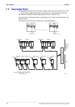
Page 129: ...al start of up to 10 outdoor units If you want to carry out sequential start connect outdoor unit outdoor unit transmission wiring as shown below The outdoor unit PC board EC is factory set to sequential start ON In the case of power supply in the same line 8 10HP outdoor unit Power supply Power supply Power supply Power supply System 8 System 1 System 7 System 6 System 5 System 4 System 3 Power s...

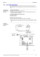
Page 130: ...rol Operation 1 Outdoor unit field setting Setting mode 1 Set low noise operation to ON Setting mode 2 Match low noise operation and demand control address with address of outdoor unit external control adaptor 2 Outdoor unit external control adaptor setting Function switch SS1 Set to BOTH or DE Address setting switches DS1 DS2 Match with outdoor unit low noise operation and demand control address ...

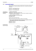
Page 131: ...rol Operation 1 Outdoor unit field setting Setting mode 1 Set low noise operation to ON Setting mode 2 Match low noise operation and demand control address with address of outdoor unit external control adaptor 2 Outdoor unit external control adaptor setting Function switch SS1 Set to BOTH or DE Address setting switches DS1 DS2 Match with outdoor unit low noise operation and demand control address ...

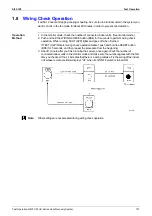
Page 132: ...o perform wiring check operation While running TEST H2P lights and goes off when finished If TEST H2P flickers wiring check operation failure push and hold the RESET button BS5 for 5 seconds and then repeat the procedure from the beginning 3 About 1 minute after you finish running the system once again check the number of connected indoor units in the monitor mode and make sure the number agrees w...

Page 133: ...other 30 minutes When the Confirmation button is pressed during additional refrigerant charge operation the operation stops 5 Disconnect the refrigerant charge hose then fully open the liquid side stop valve In service mode 1 press the MODE button for 5 seconds to enter service mode 2 8 7 7 7 7 7 7 Press the SET button to set the LED indicators to the additional refrigerant charge operation indica...

Page 134: ...the power switch of the other unit within 10 minutes 4 Conduct refrigerant recovery 5 Cancel the setting in the setting mode or cancel the mode by conducting power reset of the outdoor unit In service mode 1 press the MODE button for 5 seconds to enter service mode 2 8 7 7 7 7 7 7 Press the SET button to set the LED indicators to the refrigerant recovery mode indication 8 7 8 7 8 7 8 Press the RET...

Page 135: ... above after about 3 hours of backup operation the system again carries out malfunction detection and the system once again stops due to malfunction if an error is detected Note 1 For 2 compressor system When the STD compressor OC operates the operation continues using only the inverter compressor based on remote control reset for 3 hours only For 3 compressor system When OC operates again immedia...

Page 136: ... turned on by thermostat Emergency operation stops at the following conditions 1 Emergency operation mode is reset on outdoor unit PC board or 2 One or more indoor units connected to this outdoor unit are turned off by thermostat Setting of Emergency Mode Setting Method LED Display H1P H2P H3P H4P H5P H6P H7P Hold down the Mode button for 5 seconds to change to setting Mode 2 8 7 7 7 7 7 7 Push SE...

Page 137: ...2 Select the desired mode No with the button 3 During group control and you want to set by each individual indoor unit when mode No 20 21 22 23 25 has been selected push the time mode button and select the indoor unit No to be set Note This operation is not required when setting as a group 4 Push the button and select the first code No 5 Push the button and select the second code No 6 Push the tim...

Page 138: ...ct Mode Nos 27 and 28 Heat Reclaim Ventilation press the button and choose the Unit No to set This step is not necessary in all group unit setting 4 Press the UP button to select a Setting Switch No 5 Press the DOWN button to select a Setting Position No 6 Press the button once to enter the settings 7 Depress the button for about 1 second to return to the Normal Mode Example When setting the filte...

Page 139: ...elect the first code No 4 Pushing the button select the second code No 5 Push the timer button and check the settings 6 Push the button to return to the normal mode BRC7C type 1 When in the normal mode push the button for 4 seconds or more and operation then enters the field set mode 2 Select the desired mode No with the button 3 Pushing the button select the first code No 4 Pushing the button sel...

Page 140: ...lay time to clean air filter calculation Set when filter sign is not to be displayed Display No display 12 22 0 Optional accessories output selection field selection of output for adaptor for wiring Indoor unit turned ON by thermostat Operation output Malfunction output 1 ON OFF input from outside Set when ON OFF is to be controlled from outside Forced OFF ON OFF control External protection device...

Page 141: ... for heater thermostat OFF No duct With duct Fan off Fan L Fan off Fan L 7 Centralized individual setting Centralized Individual 8 Centralized zone interlock setting No Yes Priority on Operation 9 Pre heat time extension setting 0 30 min 60 min 90 min 18 28 0 External signal setting JC J2 Last command Priority on external input 1 Setting for direct power on Off On 2 Auto restart setting Off On 4 I...

Page 142: ...No in is used for making individual setting of each unit 3 Group number setting for centralized controller 1 Mode no 00 Group controller 2 Mode no 30 Individual controller Regarding the setting procedure refer to the section Group number setting for centralized control in the operating manual of either the on off controller or the central controller Caution 1 The setting positions are set at 01 at...

Page 143: ...FF controller displays only the group No within the range selected by the switch for setting each address 5 Push the timer button to define the selected group No 6 Push the button to return to the normal mode Even if not using a remote controller connect the remote controller when setting the group No set the group No for centralized control and disconnect after making the setting Set the group No...

Page 144: ...tting Example If you have to set the address for each unit for calculating cost etc set the mode No to 30 Caution When turning the power supply on the unit may often not accept any operation while 88 is displaying after all indications were displayed once for about 1 minute on the liquid crystal display This is not an operative fault Centoral Remote Controller F1 F2 F1 F2 F1 F2 F1 F2 P1 P2 RC RC R...

Page 145: ... controller during set time Individual Used when you want to turn on off by both central remote controller and remote controller Timer operation possible by remote controller Used when you want to turn on off by remote controller during set time and you do not want to start operation by central remote controller when time of system start is programmed How to Select Operation Mode Whether operation...

Page 146: ...N OFF control impossible by remote controller Rejection Example Rejection Example Rejection Example Rejection Acceptance 0 Rejection 10 Acceptance Example Acceptance Example 1 Example Rejection 11 OFF control only possible by remote controller Acceptance Rejection Acceptance 2 Rejection 12 Acceptance Acceptance 3 Rejection 13 Centralized Acceptance Rejection Acceptance 4 Rejection 14 Acceptance Ac...

Page 147: ...Test Operation Si33 105 136 Test Operation R407C PLUS Series Heat Recovery System ...

Page 148: ... Indoor Unit Drain Level above Limit 163 3 8 Indoor Unit Malfunction of Capacity Determination Device 164 3 9 Indoor Unit Malfunction of Thermistor R2T for Liquid Pipe 165 3 10 Indoor Unit Malfunction of Thermistor R3T for Gas Pipes 166 3 11 Indoor Unit Malfunction of Thermistor R1T for Air Inlet 167 3 12 Indoor Unit Malfunction of Thermostat Sensor in Remote Controller 168 3 13 Outdoor Unit Actua...

Page 149: ...ssor Lock 198 5 5 Outdoor Unit Malfunction of Transmission Between Inverter and Control PC Board 199 5 6 Power Supply Insufficient or Instantaneous Failure 201 5 7 Outdoor Unit Inverter Over Ripple Protection 202 5 8 Outdoor Unit Malfunction of Inverter Radiating Fin Temperature Rise Sensor 203 6 Troubleshooting OP Central Remote Controller 204 6 1 Malfunction of Transmission Between Central Remot...

Page 150: ...an M1F OFF Louver M1S OFF Drain up kit M1P OFF Humidifier Hu OFF Electronic expansion valve Y1E Closed Optional auxiliary electric heater K1R OFF Depress reset Operation ON OFF switch Operation display lamp ON Air flow rate setting display ON Air flow direction setting display ON Temperature setting display ON Indicates previous settings for air flow rate and direction and temperature NO ON OFF YE...

Page 151: ...ume of air flow Drain up kit M1P OFF after 5 minutes residual operation Frost prevention operation in progress Test run in progress Thermostat status Option Drain up kit M1P ON OFF Option Drain up kit M1P OFF after 5 minutes residual operation Electronic expansion valve Y1E OFF Thermostat on operation signal to outdoor unit Cancelled Electronic expansion valve Y1E Capacity control Thermostat ON op...

Page 152: ...nd air flow settings of the controller 8 Thermostat status Preset temperature during programme dry operation Fan in operation Swing flap Air flow direction setting Swing flap Fan MF Operating at set air flow rate Electronic expansion valve Y1E closed Drain up kit M1P OFF Auxiliary electric heater K1R OFF Humidifier Hu OFF A H10 H11 H9 No YES Option VF024 9 Fan operation When fan operation has been...

Page 153: ... Auxiliary electric heater K1R OFF Humidifier Hu ON Auxiliary electric heater K1R ON Humidifier Hu ON Fan M1F Operating at set air flow volume Fan M1F L operation Fan M1F OFF Electronic expansion valve Y1E capacity contorol Electronic expansion valve Y1E capacity contorol Electronic expansion valve Y1E open Auxiliary electric heater K1R OFF Humidifier Hu OFF NO NO NO YES YES NO YES YES H13 H12 H14...

Page 154: ...oting R407C PLUS Series Heat Recovery System 143 14 Thermostat status 15 Low discharge air temperature protection Protection is effected when the preset temperature is 24 C or lower and the opening of the electronic expansion valve is slight ...

Page 155: ...spection Test Operation button for more than 4 seconds Press Inspection Test Operation button once Press Inspection Test Operation button once Or after 30 minutes After 10 seconds Press Inspection Test Operation button once Press Inspection Test Operation button once Indoor unit settings can be made Filter sign time Air flow direction Others Following codes can be checked Malfunction codes Indoor ...

Page 156: ...eration stops due to malfunction the remote controller s operation LED blinks and malfunction code is displayed Even if stop operation is carried out malfunction contents are displayed when the inspection mode is entered The malfunction code enables you to tell what kind of malfunction caused operation to stop See page 153 for malfunction code and malfunction contents ...

Page 157: ...perations 3 and 4 Carry out operation 4 until the buzzer sounds continuously When the buzzer sounds continuously The malfunction code is set Continuous There is no malfunction The upper digit of the code changes as shown below by pushing the advance or backward button 3 Push the operation mode selector button The 0 upper digit on the left side of the malfunction code blinks 4 Malfunction code uppe...

Page 158: ...Si33 105 Troubleshooting by Remote Controller Troubleshooting R407C PLUS Series Heat Recovery System 147 ...

Page 159: ...s 3 and 4 Continue the operation in step 4 until a buzzer remains ON The continuous buzzer indicates that the malfunction code is confirmed Continuous beep No abnormality 3 Press the MODE selector button The left 0 upper digit indication of the malfunction code flashes 4 Malfunction code upper digit diagnosis Press the UP or DOWN button and change the malfunction code upper digit until the malfunc...

Page 160: ...Si33 105 Troubleshooting by Remote Controller Troubleshooting R407C PLUS Series Heat Recovery System 149 ...

Page 161: ...door unit type code Model FXYAP FXYCP FXYKP FXYFP FXYHP FXYSP FXYLP FXYMP Type VRV System Inverter K Series R407C VRV PLUS Series R407C VRV PLUS Heat recovery Series Display A A 1 A A 3 A 9 3 Outdoor model code Model RSXYP RSXYP RSEYP Unit Malfunction code Inspection Normal display No display 0 L 0 Malfunction code blinks when a malfunction occurs Unit Malfunction code Inspection Inspection mode P...

Page 162: ...elect the unit No For group control only Select the indoor unit No to be set with the time mode For wireless remote controller button 3 Make the settings required for each mode Modes 41 44 45 In case of Mode 44 45 push button to be able to change setting before setting work LCD code blinks For details refer to the table in next page 4 Define the setting contents Modes 44 45 Define by pushing the t...

Page 163: ...y each unit When you want to search for the unit No By selecting the unit No with the button you can turn the fan of each indoor unit on forced ON individually 44 Individual setting Set the fan speed and air flow direction by each unit Select the unit No with the time mode button Set the fan speed with the button Set the air flow direction with the button 45 Unit No transfer Transfer unit No Selec...

Page 164: ... can be carried out If a malfunction occurs during operation the operation lamp malfunction code and display of malfunctioning unit No let you know the contents and location of the malfunction When there is a stop due to malfunction the contents of the malfunction given below can be diagnosed by a combination of operation lamp INSPECTION display of the liquid crystal display and display of malfunc...

Page 165: ...r inlet loose connection disconnection short circuit failure 167 CJ 8 8 8 Malfunction of thermostat sensor in remote controller 168 Outdoor Unit E0 9 9 9 Actuation of safety device 169 E1 9 9 9 PC board defect 170 E1 8 7 9 PC board defect 170 E3 9 9 9 Actuation of high pressure switch 171 E4 9 9 9 Actuation of low pressure sensor 172 E9 9 9 9 Malfunction of moving part of electronic expansion valv...

Page 166: ...n valve failure 181 U1 9 9 9 Negative phase open phase 182 U2 9 9 9 Power supply insufficient or instantaneous failure 201 U4 9 9 9 Malfunction of transmission between indoor unit 183 U5 9 9 9 Malfunction of transmission between remote controller and indoor unit 184 U5 7 8 7 Failure of remote controller PC board or setting during control by remote controller U7 9 9 9 Malfunction of transmission be...

Page 167: ...between optional controllers for centralized control 206 211 MA 8 or 9 9 9 Improper combination of optional controllers for centralized control 207 212 MC 8 or 9 9 9 Address duplication improper setting 208 213 Heat Reclaim Ventilation 60 8 7 9 Overall alarm 9 9 9 Overall malfunction 64 8 7 9 Inside air thermistor error 65 8 7 9 Outside air thermistor error 6A 8 7 9 Damper system alarm 6A 9 9 9 Da...

Page 168: ...ubleshooting VF029 Actuation of external protection device Change the second code No to 01 or 02 Indoor unit PC board replacement External protection device is connected to terminals T1 and T2 of the indoor unit terminal block ON OFF input from outside mode No 12 first code No 1 has been set to external protection device input second code No 03 by remote controller YES NO NO YES Caution Be sure to...

Page 169: ...sed Causes Defect of indoor unit PC board Troubleshooting Turn power supply OFF then power ON again Does the system return to normal YES External factor other than malfunction for example noise etc Replace the indoor unit PC board V0816 NO Caution Be sure to turn off power switch before connect or disconnect connector or parts damage may be occurred ...

Page 170: ...oat switch and turn on again YES YES YES YES Defect of indoor unit PC board Loose connection of connector NO NO NO YES YES NO NO YES NO YES NO NO The float switch is connected to X18A of the indoor unit PC board NO The drain pump works when the power supply is reset for the indoor unit The drain pump is connected to X25A or terminals X8S and X9S of the indoor unit PC board The voltage of terminals...

Page 171: ...hooting Connect the wiring and turn on again Fix the wiring and turn on again YES NO NO NO YES YES Replace the indoor unit PC board Replace the fan motor Is the wiring from the fan motor securely connected to X4A and X5A on the indoor unit PC board Wiring between the indoor unit PC board and fan motor is disconnected Does the fan motor run VF031 Caution Be sure to turn off power switch before conn...

Page 172: ...oard NO NO YES NO YES NO YES YES NO Indoor unit is a model equipped with a swing flap function The swing motor works when the power supply is turned off and then back on When the air flow direction flap s cam mechanism is disconnected from the swing motor operation is normal when turned on again The connecting cable has no continuity After turning the swing flap ON and then stopping with the remot...

Page 173: ...ng turn the power supply off and then back on Replace the moving part of the electronic expansion valve YES YES NO NO Replace the connecting cable If you turn the power supply off and turn on again and it still does not help replace the indoor unit PC board NO YES The electronic expansion valve is connected to X7A of the indoor unit PC board Normal when coil check H1 of the moving part of the elec...

Page 174: ...rain pipe upward slope etc Defect of indoor unit PC board Troubleshooting Defect of indoor unit PC board Modify the drain piping YES YES Check if the humidifier unit is leaking NO NO Field drain piping has a defect such as upward sloping A humidifier unit optional accessory is installed on the indoor unit VF034 Caution Be sure to turn off power switch before connect or disconnect connector or part...

Page 175: ...ect of indoor unit PC board Troubleshooting VF035 Install a capacity setting adaptor Replace the indoor unit PC board NO NO YES YES Replace the indoor unit PC board The indoor unit PC board was replaced with a replacement PC board The indoor unit is a model that requires installation of a capacity setting adaptor when replacing the PC board Caution Be sure to turn off power switch before connect o...

Page 176: ...indoor unit PC board Troubleshooting VF036 Replace the indoor unit PC board Connect the thermistor and turn on again NO NO Replace the thermistor R2T YES YES Connector is connected to X12A of the indoor unit PC board Resistance is normal when measured after disconnecting the thermistor R2T from the indoor unit PC board 3 5kΩ 360kΩ Caution Be sure to turn off power switch before connect or disconne...

Page 177: ... of indoor unit PC board Troubleshooting VF037 Replace the indoor unit PC board Connect the thermistor and turn on again NO NO Replace the thermistor R3T YES YES Connector is connected to X11A of the indoor unit PC board Resistance is normal when measured after disconnecting the thermistor R3T from the indoor unit PC board 0 6kΩ 360kΩ Caution Be sure to turn off power switch before connect or disc...

Page 178: ... of indoor unit PC board Troubleshooting Replace the indoor unit PC board Connect the thermistor and turn on again NO NO Replace the thermistor R1T YES YES Connector is connected to X13A of the indoor unit PC board Resistance is normal when measured after disconnecting the thermistor R1T from the indoor unit PC board 7 2kΩ 112kΩ VF038 Caution Be sure to turn off power switch before connect or disc...

Page 179: ...es Defect of remote controller thermistor Defect of remote controller PC board Troubleshooting Turn power supply OFF then power ON again Is CJ displayed on the remote controller YES Replace remote controller External factor other than equipment malfunction for example noise etc VF039 NO Caution Be sure to turn off power switch before connect or disconnect connector or parts damage may be occurred ...

Page 180: ... of capacitor etc VF040 Connector or terminal is connected to X8A X9A and X80A of the outdoor unit PC board A1P Contacts F2C X1S X2S are open Connect the connector or terminal and turn on again Actuation of magnet switch OC for standard compressor H1 Actuation of fan motor safety thermostat H2 YES NO NO YES Contact Q1M X8A or Q2M X9A is open NO YES Operation is normal when turned on again by remot...

Page 181: ...5 170 Troubleshooting R407C PLUS Series Heat Recovery System 3 14 Outdoor Unit PC Board Defect Remote Controller Display E1 Supposed Causes Defect of outdoor unit PC board A1P Troubleshooting Replace outdoor unit PC board A1P ...

Page 182: ...tdoor unit PC board s connector is disconnected Is the outdoor unit heat exchanger dirty Defect of outdoor fan Is the refrigerant over charged Is the stop valve closed Operation is normal when turned on again by remote controller Replace outdoor unit PC board A1P Actuation of high pressure switch H1 YES YES There was an instantaneous power failure or a past safety device actuated Re check refriger...

Page 183: ...pressure voltage characteristics table on P243 V2735 Low pressure at stop due to malfunction is 0 0 MPa Measure the voltage VL of X21A pin No 2 3 of outdoor PC board A1P H1 Is the relationship between low voltage and VL normal Out of gas refrigerant system clogging wiring and piping wrong connection Replace the low pressure sensor Replace outdoor unit PC board A1P NO NO YES YES Is the stop valve o...

Page 184: ...tor pins Normal Continuity Approx 300Ω Continuity Approx 150Ω No continuity VF043 Electronic expansion valve is connected to X14A of outdoor unit PC board A1P Normal when coil check H1 of the moving part of the electronic expansion valve is checked The connecting cable is short circuited or disconnected Replace the connecting cable Replace outdoor unit PC board A1P NO NO NO Replace the moving part...

Page 185: ...wrong connection of the injection solenoid valves Y3S Y6S and Y7S Is there a wrong connection of the discharge pipe thermistor R31T inverter side to X16A R32T standard side to X17A and R33T standard side to X21A for 24 30 class Are the characteristics of the discharge pipe thermistor normal R31T R32T or R33T For the characteristics table Replace outdoor unit PC board A1P or A3P for 24 30 class Con...

Page 186: ...oting The alarm indicator is displayed when the fan only is being used also VF045 Resistance is normal when measured after disconnecting the thermistor R1T from the outdoor unit PC board 3 5kΩ 360kΩ Connector is connected to X20A of outdoor PC board A1P Replace outdoor unit PC board A1P Connect the thermistor and turn on again NO NO Replace the thermistor R1T YES YES Caution Be sure to turn off po...

Page 187: ...when the fan is being used also Note 16 20 HP class R31T R32T A1P 24 30 HP class R31T R32T A1P R33T A3P VF046 Resistance is normal when measured after disconnecting the thermistor from the outdoor unit PC board 3 5kΩ 400kΩ Replace outdoor unit PC board A1P or A3P Connect the thermistor and turn on again NO NO Replace the thermistor R31T R32T or R33T YES YES Connector is connected to X16A X17A or X...

Page 188: ...oubleshooting The alarm indicator is displayed when the fan is being used also VF047 Resistance is normal when measured after disconnecting the thermistor R6T from the outdoor unit PC board 3 5kΩ 360kΩ Replace outdoor unit PC board A1P Connect the thermistor and turn on again NO NO Replace the thermistor R6T YES YES Connector is connected to X13A of outdoor unit PC board A1P Caution Be sure to tur...

Page 189: ...n is being used also Note 16 20HP class R21T R22T A1P 24 30HP class R21T R22T A1P R23T A3P VF048 Resistance is normal when measured after disconnecting the thermistor R21T R22T or R23T from the outdoor unit PC board 3 5kΩ 360kΩ Replace outdoor unit PC board A1P or A3P Connect the thermistor and turn on again NO NO Replace the thermistor R21T R22T or R23T YES YES Connector is connected to X18A 19A ...

Page 190: ...nt 2 Refer to pressure sensor pressure voltage characteristics table on P243 VF049 The relationship between the H1 VH and high pressure is normal see H2 when voltage is measured between X22A pins 1 and 3 of outdoor unit PC board A1P see H1 Replace the high pressure sensor Connect the high pressure sensor and turn on again NO NO Replace outdoor unit PC board A1P YES YES The high pressure sensor is ...

Page 191: ...fer to pressure sensor pressure voltage characteristics table on P243 VF050 The relationship between the H1 VH and low pressure is normal see H2 when voltage is measured between X21A pins 2 and 3 of outdoor unit PC board A1P see H1 Replace the low pressure sensor Connect low pressure sensor property and restart system NO NO Replace outdoor unit PC board A1P YES YES The low pressure sensor is conne...

Page 192: ...rmistor R6T and coil thermistor R2T disconnected from the outdoor unit PC board Out of gas or refrigerant system is clogged Requires check of refrigerant system Replace the thermistor Replace the outdoor unit PC board A1P YES NO NO Out of gas or refrigerant system is clogged Requires check of refrigerant system Replace low outdoor unit PC board YES YES NO Cooling Low pressure is 1 0 kg cm 0 098 MP...

Page 193: ...053 Operation is normal if one place of power supply line phase is replaced Fix the open phase Requires inspection of field power supply section Negative phase Disposal of the problem is completed by phase replacement Replace outdoor unit PC board A1P YES YES NO NO There is an open phase at the power supply terminal section X1M of the outdoor unit Caution Be sure to turn off power switch before co...

Page 194: ...door outdoor unit transmission wiring YES NO NO YES Has the indoor or outdoor unit PC board been replaced or has the indoor outdoor or outdoor outdoor unit transmission wiring been modified All indoor unit remote controllers of the same refrigerant system display U4 NO Outdoor unit PC board microcomputer monitor HAP blinks NO NO Operation ready lamp H2P is blinking Is indoor outdoor and outdoor ou...

Page 195: ...e controller to SLAVE turn the power supply off once and then back on There is possibility of malfunction caused by noise Check the surrounding area and turn on again NO NO Using 2 remote controllers control All indoor PC board microcomputer monitors blink YES Multi core cable is used for the indoor unit remote controller transmission wiring Operation returns to normal when the power is turned off...

Page 196: ...t selection is unified C H SELECT is set to MASTER NO Is the indoor outdoor unit transmission wiring normal C H SELECT is set to SLAVE YES NO Check and see if the following items are normal NO Does a malfunction occur when the cool heat selector is set to IND YES Set C H SELECT to IND The cool heat unified address for outdoor units in outdoor outdoor unit transmission is duplicated Set the address...

Page 197: ...troller PC board Troubleshooting VF057 SS1 of both remote controllers is set to SUB Set SS1 to MAIN the power supply off once and then back on Set one remote controller to MAIN the power supply off once and then back on Turn the power off and then back on If a malfunction occurs replace the remote controller PC board YES YES YES NO NO NO Using 2 remote controllers control SS1 of remote controller ...

Page 198: ...e diagnosis for U5 malfunction code Re diagnose by display after passage of 2 minutes or more NO NO Refer to failure diagnosis for U4 malfunction code YES YES U9 has been displayed for 2 minutes or more NO Turn on all indoor units Refer to failure diagnosis for A1 malfunction code NO YES The A1 display blinks on the remote controllers of other units within the same refrigerant system NO Refer to f...

Page 199: ... on the type of outdoor unit RSEYP16 20KJY1 20 units RSEYP24 30KJY1 32 units VF059 The total of indoor units displaying UA and indoor units connected to the same refrigerant system is 20 or 32 units or less H Replace outdoor unit PC board A1P Normal NO NO There are too many indoor units within the same refrigerant system Push and hold the RESET button on the outdoor unit PC board for 5 seconds YES...

Page 200: ... connected to HFC R407C system Reason Operation disallowed due to insufficient pressure proof in R22 indoor unit 2 When HFC indoor unit is connected to R22 system Reason Operation disallowed to prevent contamination of another system by HFC indoor unit operated previously with R22 system If HFC indoor unit that was operated with R22 system is removed and connected to another HFC system it can cont...

Page 201: ...ntroller Defect of indoor unit PC board Troubleshooting VF060 Replace indoor unit PC board Address duplication of central remote controller The setting must be changed so that the central remote control address is not duplicated YES NO Optional controllers for centralized control are connected to the indoor unit Caution Be sure to turn off power switch before connect or disconnect connector or par...

Page 202: ... been off for more than 12 hours or if it is not carried out after running all connected indoor units in the fan mode for at least an hour VF061 Is indoor outdoor and outdoor outdoor unit transmission wiring normal Replace indoor unit PC Wiring check may not have been carried out successfully After fixing incorrect wiring push and hold the RESET button on the outdoor unit PC YES NO YES NO NO YES W...

Page 203: ...t time after installation or after an indoor or outdoor unit PC board has been replaced Is indoor outdoor and outdoor outdoor unit transmission wiring normal YES Normal NO Does a malfunction occur NO Does a UH malfunction occur for all indoor units in the system YES NO Does a malfunction occur even after 12 minutes elapses from the time when electricity is introduced to indoor and outdoor units YE...

Page 204: ...er unit Other L4 Radiator fin temperature rise Is the intake port of the radiator fin clogged L5 Instantaneo us over current Inspect the compressor L8 Electronic thermostat Inspection the compressor and refrigerant system L9 Stall prevention Inspection the compressor and refrigerant system LC Malfunction of transmission between inverter PC board and outdoor unit PC board Inspect the connection bet...

Page 205: ...erely entering the five minutes standby while retry is attempted the prescribed number of times If the number of retry times is exceeded within 60 minutes malfunction is ascertained and the corresponding malfunction code is displayed on the indoor unit remote controller 9 Blink 8 On 7 Off LED A 1 2 3 4 Malfunction contents Retry times 9 7 7 7 7 Normal 9 7 7 7 8 Malfunction of fin thermistor 3 9 8 ...

Page 206: ...of fin thermistor Troubleshooting VF063 Characteristic check of the radiator fin thermistor Refer to thermistor characteristics table Defect of power unit radiation Intake port is clogged Radiator fin is dirty Outdoor temperature is high NO Replace the thermistor YES Abnormal Is reset possible Reset and operate Normal Replace the inverter unit NO YES Temperature of the radiator fin rises Actuates ...

Page 207: ...erter output voltage is not balanced Normal if within 8V Note Must be measured when frequency is stable Replace the compressor Compressor inspection Inspect according to the diagnosis procedure for odd noises vibration and operating status of the compressor NO Replace the inverter unit YES YES Correct power supply YES The compressor s coil is disconnected or the insulation is defective NO NO Disco...

Page 208: ...mpressor overload Inspection of the compressor and refrigerant system is required Compressor inspection Inspect according to the diagnosis procedure for odd noises vibration and operating status of the compressor NO Replace the inverter unit YES NO Reset and restart NO The secondary current of the inverter is higher than 27 5A for each phase Replace the compressor NO YES Compressor inspection The ...

Page 209: ...measured when frequency is stable Unsatisfactory pressure equalization Check refrigerant system Compressor inspection Inspect according to the diagnosis procedure for odd noises vibration and operating status of the compressor YES Replace the inverter unit NO NO Reset and restart NO The difference between high and low pressure when starting is 2kg cm2 0 196 MPa YES YES Disconnect the connection be...

Page 210: ... Board Remote Controller Display LC Supposed Causes Malfunction of connection between the inverter unit and outdoor unit PC board Defect of outdoor unit PC board transmission section Defect of inverter unit Defect of noise filter NF1 Lack of phase on power supply during outdoor unit operation External factor Noise etc Horse power setting error on outdoor unit PC board ...

Page 211: ...se filter Z1F for disconnection and check the power supply wiring or the inverter unit Replace inverter PC board When the LC malfunction occur again replace control PC board YES YES Is the outdoor unit P C BOARD replaced Confirm the horse power setting on outdoor unit PC board was done and reset power YES The microcomputer monitor green on sub board is blinking NO NO Check the sub board power and ...

Page 212: ...Is 220 240 V at the connector of X1A in A2P Replace the inverter unit A2P Replace the inverter unit A2P There was an instantenious power failure or noise etc Replace the inverter unit A2P YES NO NO Does the voltage between terminals P and N gradually rise to 339 VDC Y1 after turning on U2 blinks again Monitor field power supply The voltage between the P and N terminals on Power unit in PCB A2P is ...

Page 213: ...er supply voltage record power supply voltage between 3 phases L1 L2 L2 L3 L3 L1 for about one continuous week Open phase Normalize field cause Power supply voltage imbalance Explanation for users Fix power supply voltage imbalance YES YES NO Imbalance in supplied voltage is in excess of 20 V Y1 H1 Open phase When voltage monitoring is possible H1 Measure voltage at the X1M power supply terminal b...

Page 214: ...es Defect of radiator fin temperature sensor Defect of inverter unit Troubleshooting VF070 After resetting restart YES YES Is the resistance of thermistor correct Is the resetting possible Replace radiation fin thermistor Measure the resistance of radiation fin thermistor NO Replace inverter PC board NO Caution Be sure to turn off power switch before connect or disconnect connector or parts damage...

Page 215: ...g disconnected or wired incorrectly Is the transmission wiring with the master controller disconnected or wired incorrectly Is the master controller s connector for setting master controller disconnected Set the group No correctly Replace indoor unit PC board Fix the wiring correctly Fix the wiring correctly Connect the connector correctly Replace the central PC board Reset power supply simultaneo...

Page 216: ... Controller Troubleshooting R407C PLUS Series Heat Recovery System 205 6 2 PC Board Defect Remote Controller Display M1 Supposed Causes Defect of central remote controller PC board Troubleshooting Replace the central remote controller PC board ...

Page 217: ...on off using each optional controllers for centralized control and replace the PC board of the one that is unable to control the indoor unit NO NO Fix the wiring correctly YES YES Has a once connected optional controller for centralized control been disconnected or its address changed Turn on power supply for all optional controllers for centralized control Reset power supply simultaneously for al...

Page 218: ...chedule timer s individual combined connector and reset the power supply for all optional controllers for centralized control simultaneously Arrange so that the connector for setting master control is connected to one controller for centralized control and reset the power supply for all optional controllers for centralized control simultaneously Disconnect the connector for setting master control ...

Page 219: ...ress duplication of central remote controller Troubleshooting Are two or more central remote controllers connected Disconnect all central remote controllers except one and reset the power supply of the central remote controller Reset power supply of the central remote controller NO YES VF074 Caution Be sure to turn off power switch before connect or disconnect connector or parts damage may be occu...

Page 220: ...g disconnected or wired incorrectly Is the transmission wiring with the master controller disconnected or wired incorrectly Is the master controller s connector for setting master controller disconnected Set the group No correctly Replace indoor unit PC board Fix the wiring correctly Fix the wiring correctly Connect the connector correctly Replace the central PC board Reset power supply simultaneo...

Page 221: ...splay M1 Supposed Causes Defect of schedule timer PC board Troubleshooting Reset power supply Does the system return to normal YES External factor other than equipment malfunction noise etc Replace the indoor unit PC board V0843 NO Caution Be sure to turn off power switch before connect or disconnect connector or parts damage may be occurred ...

Page 222: ...f using each optional controllers for centralized control and replace the PC board of the one that is unable to control the indoor unit YES NO Fix the wiring correctly YES NO Has a once connected optional controller for centralized control been disconnected or its address changed Turn on power supply for all optional controllers for centralized control Reset power supply simultaneously for all opt...

Page 223: ...tive and must be replaced Reset the power supply for all optional controllers for centralized control simultaneously YES YES NO Is the schedule timer connected Are there two or more optional controllers for centralized control connected with the connector for setting master control YES Is the schedule timer s individual combined connector connected NO NO Cannot be used in combination with a wiring...

Page 224: ...ses Address duplication of optional controller for centralized control Troubleshooting VF078 Are two or more schedule timers connected Reset the power supply for the schedule timer Disconnect all schedule timers except one and reset the schedule timer s power supply YES NO Caution Be sure to turn off power switch before connect or disconnect connector or parts damage may be occurred ...

Page 225: ...er disconnected or wired incorrectly Is the master controller s connector for setting master controller disconnected Set the group No correctly Replace indoor unit PC board Fix the wiring correctly Fix the wiring correctly Connect the connector correctly Replace the central PC board Reset power supply for all optional controllers for centralized control simultaneously NO YES NO YES YES NO YES Turn...

Page 226: ...r s switch for setting each address and reset the power supply of the unified ON OFF controller Refer to failure diagnosis for central remote controller or schedule timer NO YES YES NO NO Fix the wiring correctly Set reset switch to normal NO NO YES YES YES Is the power supply turned on for all optional controllers for centralized control Reset power supply simultaneously for all optional controll...

Page 227: ...tralized control simultaneously Arrange so that the connector for setting master control is connected to one controller for centralized control and reset the power supply for all optional controllers for centralized control simultaneously Disconnect the connector for setting master control from the master controller connect to another optional controller for centralized control and simultaneously ...

Page 228: ...the switch for setting each address set correctly Is the transmission wiring disconnected or wired incorrectly Replace the PC board of the unified ON OFF controller Fix the wiring correctly Set by remote controller the central control address for all indoor units connected to the central control line YES YES Set the switch for setting each address correctly and simultaneously reset the power suppl...

Page 229: ...Troubleshooting OP Unified ON OFF Controller Si33 105 218 Troubleshooting R407C PLUS Series Heat Recovery System ...

Page 230: ...ing Diagram 220 1 1 Outdoor Unit 220 1 2 BS Unit 222 1 3 Indoor Unit 224 2 Wiring Diagram 225 2 1 Outdoor Unit 225 2 2 BS Unit 227 2 3 Indoor Unit 228 3 Characteristics 240 3 1 R407C Characteristics 240 3 2 Thermistor Resistance Temperature Characteristics 241 3 3 Pressure Sensor 243 3 4 Method of Replacing The Inverter s Power Transistors and Diode Modules 244 4 Precautions in Servicing The Model...

Page 231: ...Piping Diagram Si33 105 220 Appendix R407C PLUS Series Heat Recovery System 1 Piping Diagram 1 1 Outdoor Unit RSEYP16 18 20KJY1 3D031937 ...

Page 232: ...Si33 105 Piping Diagram Appendix R407C PLUS Series Heat Recovery System 221 RSEYP24 26 28 30KJY1 3D031938 ...

Page 233: ...Piping Diagram Si33 105 222 Appendix R407C PLUS Series Heat Recovery System 1 2 BS Unit BSVP100KJV1 BSVP160KJV1 4D014497A 4D014498A ...

Page 234: ...Si33 105 Piping Diagram Appendix R407C PLUS Series Heat Recovery System 223 BSVP250KJV1 4D014499A ...

Page 235: ... R407C PLUS Series Heat Recovery System 1 3 Indoor Unit FXYFP FXYCP FXYKP FXYSP FXYMP FXYHP FXYAP FXYLP FXYLMP DU220 602D Heat exchanger Gas piping connection port Liquid piping connection port Fan Electronic expansion valve Filter Filter ...

Page 236: ...Si33 105 Wiring Diagram Appendix R407C PLUS Series Heat Recovery System 225 2 Wiring Diagram 2 1 Outdoor Unit RSEYP16 18 20KJY1 3D031466 ...

Page 237: ...Wiring Diagram Si33 105 226 Appendix R407C PLUS Series Heat Recovery System RSEYP24 26 28 30KJY1 3D031467 ...

Page 238: ...Si33 105 Wiring Diagram Appendix R407C PLUS Series Heat Recovery System 227 2 2 BS Unit 3D014829B ...

Page 239: ...Wiring Diagram Si33 105 228 Appendix R407C PLUS Series Heat Recovery System 2 3 Indoor Unit FXYFP32 40 50 63 80 125KV1 3D005759B ...

Page 240: ...Si33 105 Wiring Diagram Appendix R407C PLUS Series Heat Recovery System 229 FXYFP32 40 50 63 80 100 125KVE 3D020238B ...

Page 241: ...Wiring Diagram Si33 105 230 Appendix R407C PLUS Series Heat Recovery System FXYCP20 25 32 63KV1 DU229 5139C ...

Page 242: ...Si33 105 Wiring Diagram Appendix R407C PLUS Series Heat Recovery System 231 FXYCP40 50 80 125KV1 DU230 522C ...

Page 243: ...Wiring Diagram Si33 105 232 Appendix R407C PLUS Series Heat Recovery System FXYKP25 32 40 63KV1 DU227 544C ...

Page 244: ...Si33 105 Wiring Diagram Appendix R407C PLUS Series Heat Recovery System 233 FXYSP20 25 32 40 50 63KV1 DU227 545E ...

Page 245: ...Wiring Diagram Si33 105 234 Appendix R407C PLUS Series Heat Recovery System FXYSP80 100 125KV1 DU230 519D ...

Page 246: ...Si33 105 Wiring Diagram Appendix R407C PLUS Series Heat Recovery System 235 FXYMP40 50 63 80 100 125KV1 DU229 5140C ...

Page 247: ...Wiring Diagram Si33 105 236 Appendix R407C PLUS Series Heat Recovery System FXYMP200 250KV1 3D011012B ...

Page 248: ...Si33 105 Wiring Diagram Appendix R407C PLUS Series Heat Recovery System 237 FXYHP32 63 100KV1 DU228 531C ...

Page 249: ...Wiring Diagram Si33 105 238 Appendix R407C PLUS Series Heat Recovery System FXYAP20 25 32 40 50 63KV1 DU221 561F ...

Page 250: ...Si33 105 Wiring Diagram Appendix R407C PLUS Series Heat Recovery System 239 FXYLP20 25 32 40 50 63KV1 FXYLMP20 25 32 40 50 63KV1 3D003923E ...

Page 251: ...0 9 36 4 2 30 52 7 57 4 0 35 0 6 1 35 32 0 37 6 2 35 53 7 58 3 0 40 2 5 1 40 33 2 38 7 2 40 54 7 59 2 0 45 1 1 5 4 1 45 34 4 39 9 2 45 55 6 60 2 0 50 1 4 7 9 1 50 35 6 41 1 2 50 56 6 61 1 0 55 3 9 10 3 1 55 36 8 42 2 2 60 58 4 62 8 0 60 6 4 12 7 1 60 38 1 43 4 2 70 60 0 64 3 0 65 8 7 14 9 1 65 39 3 44 6 2 80 61 6 65 9 0 70 10 6 16 8 1 70 40 5 45 7 2 90 63 2 67 4 0 75 12 6 18 7 1 75 41 7 46 9 3 00 ...

Page 252: ... 85 49 83 25 45 8 71 8 54 4 81 08 78 97 46 8 37 8 21 3 76 93 74 94 47 8 05 7 90 2 73 01 71 14 48 7 75 7 60 1 69 32 67 56 49 7 46 7 31 0 65 84 64 17 50 7 18 7 04 1 62 54 60 96 51 6 91 6 78 2 59 43 57 94 52 6 65 6 53 3 56 49 55 08 53 6 41 6 53 4 53 71 52 38 54 6 65 6 53 5 51 09 49 83 55 6 41 6 53 6 48 61 47 42 56 6 18 6 06 7 46 26 45 14 57 5 95 5 84 8 44 05 42 98 58 5 74 5 43 9 41 95 40 94 59 5 14 5...

Page 253: ...233 14 71 33 92 33 35 121 7 26 7 16 22 228 05 223 08 72 32 78 32 23 122 7 06 6 97 23 218 24 213 51 73 31 69 31 15 123 6 87 6 78 24 208 90 204 39 74 30 63 30 12 124 6 69 6 59 25 200 00 195 71 75 29 61 29 12 125 6 51 6 42 26 191 53 187 44 76 28 64 28 16 126 6 33 6 25 27 183 46 179 57 77 27 69 27 24 127 6 16 6 08 28 175 77 172 06 78 26 79 26 35 128 6 00 5 92 29 168 44 164 90 79 25 91 25 49 129 5 84 5...

Page 254: ...re PL High Pressure PH VH 0 5 0 98 Low Pressure PL VL 0 5 0 98 3 PH Detected Pressure High Side MPa PL Detected Pressure Low Side MPa VH Output Voltage High Side VDC VL Output Voltage Low Side VDC 0 5 1 0 5 0 1 2 3 4 VDC Output Voltage VH VL 10 2 1 0 15 3 1 5 30 6 3 0 25 5 2 5 20 4 2 0 kg cm MPa Detected Pressure PH PL V0818 ...

Page 255: ...Inverter s Power Transistors and Diode Modules Decision according to continuity check by analog tester Before checking disconnect the electric wiring connected to the power transistor and diode module Power Transistor On Inverter PC Board Decision If other than given above the power unit is defective and must be replaced Note If using a digital tester and continuity may be reversed ...

Page 256: ...istics Appendix R407C PLUS Series Heat Recovery System 245 Diode Module Decision If other than given above the diode module is defective and must be replaced Note If using a digital tester and continuity may be reversed ...

Page 257: ...ility with conventional tools and materials Pipe cutter Refrigerant piping work Cutting pipes Interchangeable Flaring tool Flaring pipes Refrigerant oil Applying on flared spots Specified ether oil ester oil alkyl benzene oil or their mixture to be used Torque wrench Connecting flare nut Interchangeable Pipe expander Expanding pipes at connections Pipe bender Bending pipes Nitrogen Air tightness t...

Page 258: ...ings to come into the pipes To avoid leak apply a proper amount of refrigerant oil over the inner and outer surfaces of each flared section As the refrigerant oil be sure to use synthetic oil ether oil ester oil alkyl benzene oil or their mixture Charging refrigerant Be sure to charge the new type refrigerant in liquid phase via the service port of the liquid side stop valve outdoor unit At this t...

Page 259: ...Precautions in Servicing The Models with New type Refrigerant Si33 105 248 Appendix R407C PLUS Series Heat Recovery System ...

Page 260: ...t Computer Integrate Control Blinks Repeats Single Blink 215 Drain Level above Limit 163 Drain Pump Control 97 Drooping due to Outdoor Temperature 83 E E0 169 E1 170 E3 171 E4 172 E9 173 Electric heater setting 130 Emergency Operation 125 Equalizing Startup Control 60 Error of External Protection Device 157 Excessive Number of Indoor Units 188 External input terminal function selection between J1 ...

Page 261: ...of Thermistor R6T for Suction Pipe 177 Malfunction of Thermistor for Outdoor Air R1T 175 Malfunction of Thermostat Sensor in Remote Controller 168 Malfunction of Transmission Between Central Remote Controller and Indoor Unit 204 209 Malfunction of Transmission Between Indoor and Outdoor Units in the Same System 187 Malfunction of Transmission Between Indoor Units 183 Malfunction of Transmission Be...

Page 262: ...30 Setting for direct power on 130 Setting Items 112 Setting Mode 1 111 Setting Mode 2 112 Setting Modes 109 Setting switch No 130 Standby due to Pc 53 Standby due to Pe 54 Standby due to Td 54 Startup Control 56 STD Compressor Operation 67 T Test Operation 104 The INSPECTION TEST Button 144 Thermistor Resistance Temperature Characteristics 241 Thermostat Sensor in Remote Controller 100 U U0 181 U...

Page 263: ...Si33 105 iv Index ...
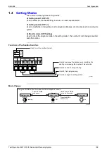
Page 264: ...ler 98 When the Float Switch is Tripped During Cooling OFF by Thermostat 97 When the Float Switch is Tripped During Heating Operation 98 When the Float Switch is Tripped While the Cooling Thermostat is ON 97 Drooping due to Outdoor Temperature 83 E Equalizing Startup Control 60 Error of External Protection Device 157 Excessive Number of Indoor Units 188 F Fan Location 96 Fan Motor M1F Lock Overloa...

Page 265: ...ontroller and Indoor Unit 204 209 Malfunction of Transmission Between Indoor and Outdoor Units in the Same System 187 Malfunction of Transmission Between Indoor Units 183 Malfunction of Transmission Between Inverter and Control PC Board 199 Malfunction of Transmission Between Master and Slave Remote Controllers 186 Malfunction of Transmission Between Optional Controllers for Centralized Control 20...

Page 266: ...TION TEST Button 144 Thermostat Sensor in Remote Controller Cooling 100 Heating 101 Transmission terminal 108 Turn Power On 104 U Unit No transfer 152 V Variation of Temperature Control Mode 88 W Wiring Check Operation 121 Wiring Diagram BS Unit 227 FXYAP20 25 32 40 50 63KV1 238 FXYCP20 25 32 63KV1 230 FXYCP40 50 80 125KV1 231 FXYFP32 40 50 63 80 100 125KVE 229 FXYFP32 40 50 63 80 125KV1 228 FXYHP...

Page 267: ... 8323 Japan Tokyo office Shinjuku Sumitomo Bldg 6 1 Nishi Shinjuku 2 chome Shinjuku ku Tokyo 163 0235 Japan Zandvoordestraat 300 B 8400 Oostende Belgium For further improvement specifications or designs are subject to change without prior notice Printed in Singapore 01 2002 AK ...

Reviews: