• Outdoor Units • VRV HEAT RECOVERY • REYHQ16-24P
1
5
• VRV Systems • Outdoor Units
27
5
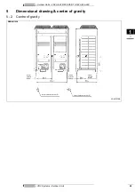
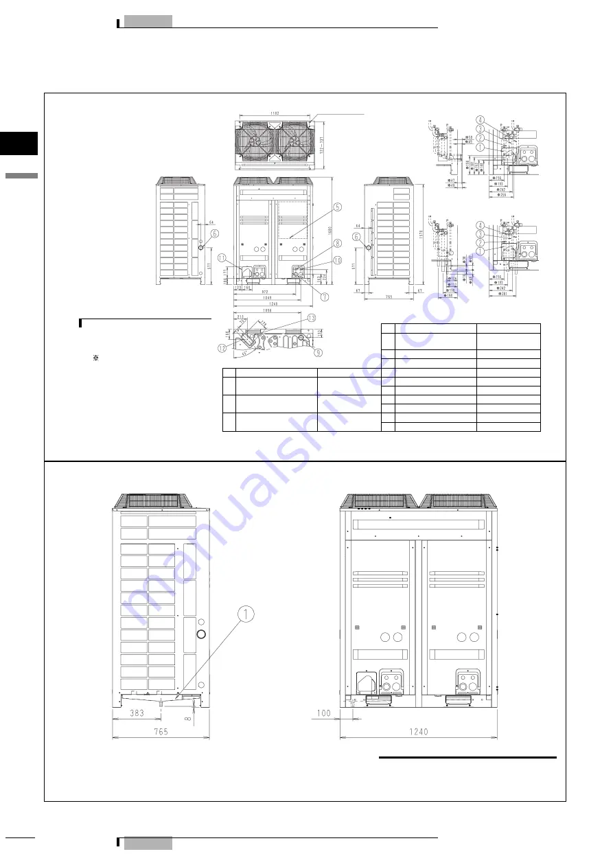
Dimensional drawing & centre of gravity
5 - 1
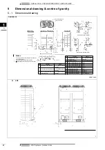
Dimensional drawing
REMHQ12P8
3D057585A
(Pi
tc
h of foundati
on bol
t hol
es
)
(DETAIL FOR FRONT SIDE)
(DETAIL FOR BOTTOM SIDE)
(knock-out hole)
(knock-out hole)
(knock-out hole)
(knock-out hole)
(knock-out hole): pressure equalizer pipe only.
N
OTES
1
For piping connection method (front and bottom sides) see
the installation manual.
2
Piping connection diameter for field connection.
3
shows the dimensions after fixing the accesory pipes.
(knock-out hole)
4-15 x 22.5-mm-Oblong holes
(foundation bolt hole)
No.
Parts name
Remarks
4
Pressure equalizer pipe
connection port.
∅
19.1
Brazing connection.
See note 2
5
Grounding terminal
inside of switch box (M8)
6
Power cord routing hole (side)
∅
62
No.
Parts name
Remarks
7
Power cord routing hole (front)
∅
45
1
Liquid pipe connection port.
∅
12.7
Brazing connection.
See note 2
8
Power cord routing hole (front)
∅
27
9
Power cord routing hole (bottom)
∅
65.5
2
Suction gas pipe connection port.
∅
28.6 Brazing connection.
See note 2
10
Wire routing hole (front)
∅
27
11
Pipe routing hole (front)
See note 1.
3
High and low pressure gas pipe
connection port
∅
22.2
Brazing connection.
See note 3
12
Pipe routing hole (bottom)
See note 1.
13
Pipe routing hole (bottom)
∅
50 See note 1.
(Pitch of foundation bolt holes)
G
H
2P8


