Field Settings for Indoor Unit
SiUS371901E
171
Field Settings and Test Operation
FXTQ-TA, CXTQ-TA
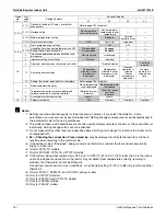
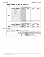
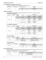
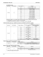
When the Second Code No. is set to
02
, room temperature is controlled by the remote sensor thermistor.
When the Second Code No. is set to
03
, room temperature is controlled by the remote controller thermistor.
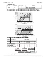
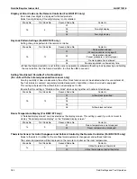
When the unit is equipped with an infrared presence/floor sensor:
∗
Refer to
Compensating the Temperature around People
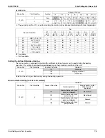
Mode No.
First Code No.
Second Code No.
Contents
10 (20)
2
01
—
02
Remote sensor thermistor only
03
Remote controller thermistor only
20
22
24
26
28
30
32
34
36
21
19
17
23
25
27
29
31
33
35
37
(˚C)
(˚C)
14
16
18
20
22
24
26
28
30
32
(˚C)
(˚C)
68
71.6
75.2
78.8
82.4
86
89.6
93.2
96.8
57.2
60.8
64.4
68
71.6
75.2
78.8
82.4
86
89.6
(˚F)
(˚F)
14
16
18
20
22
24
26
28
30
32
34
66.2
62.6
69.8 73.4
77
80.6 84.2 87.8 91.4
95
98.6
(˚F)
(˚F)
57.2 60.8
64.4
68
71.6 75.2
78.8 82.4
86
89.6 93.2
In cooling
In heating
Suction air temperature
Suction air temperature
Suction air
thermistor
Suction air
thermistor
Suction air
thermistor
Suction air
thermistor
Suction air
thermistor
Suction air
thermistor
Suction air
thermistor
Suction air
thermistor
Remote controller
thermistor
Remote controller
thermistor
Remote controller
thermistor
Remote controller
thermistor
Set temper
ature
Set temper
ature
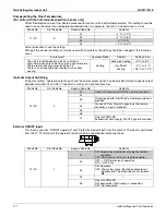
Mode No.
Second Code No.
10 (20)
2
01
02
02
02
02
03
11 (21)
8
01
01
02
03
04
01
The thermistor to be used
Remote controller thermistor
9
—
—
—
—
9
Suction air thermistor
9
9
9
9
9
—
Infrared presence/floor sensor
—
—
9
9
9
—
First Code No.
The infrared
presence/floor
sensor is not used
Priority given to
the suction air
temperature (
∗
)
Priority given to the
floor temperature (
∗
)
Only the suction air
thermistor is used
Standard setting
(Factory setting)
Only the remote
controller thermistor
is used
Summary of Contents for REYQ-XA
Page 1: ...Service Manual SiUS371901E REYQ72 456XATJU REYQ72 456XAYDU REYQ72 432XAYCU Heat Recovery 60 Hz...
Page 415: ...SiUS371901E Wiring Diagrams Appendix 402 REYQ144 168XATJU 2D119206A...
Page 416: ...Wiring Diagrams SiUS371901E 403 Appendix REYQ72 96 120XAYDU 2D119207B...
Page 417: ...SiUS371901E Wiring Diagrams Appendix 404 REYQ144 168XAYDU 2D119208B...
Page 418: ...Wiring Diagrams SiUS371901E 405 Appendix REYQ72 96 120 144 168XAYCU 2D119209A...
Page 421: ...SiUS371901E Wiring Diagrams Appendix 408 FXZQ05 07 09 12 15 18TAVJU 3D110443A...
Page 423: ...SiUS371901E Wiring Diagrams Appendix 410 FXEQ07 09 12 15 18 24PVJU 3D098557A...
Page 425: ...SiUS371901E Wiring Diagrams Appendix 412 FXSQ05 07 09 12 15 18 24 30 36 48 54TAVJU C 3D110467C...
Page 426: ...Wiring Diagrams SiUS371901E 413 Appendix FXMQ07 09 12 15 18 24 30 36 48 54PBVJU 3D093209B...
Page 428: ...Wiring Diagrams SiUS371901E 415 Appendix FXHQ12 24 36MVJU 3D048116C...
Page 429: ...SiUS371901E Wiring Diagrams Appendix 416 FXAQ07 09 12 18 24PVJU C 3D075354D...
Page 435: ...SiUS371901E Wiring Diagrams Appendix 422 VAM1200GVJU 3D073270D...
Page 437: ...SiUS371901E Wiring Diagrams Appendix 424 1 4 2 Multi Branch Selector Unit BS4Q54TVJ 3D089123B...
Page 438: ...Wiring Diagrams SiUS371901E 425 Appendix BS6 8Q54TVJ 2D089122B...
Page 439: ...SiUS371901E Wiring Diagrams Appendix 426 BS10 12Q54TVJ 2D089121B...
Page 440: ...Revision History Month Year Version Revised contents 04 2019 SiUS371901E First edition...

