Field Settings for Outdoor Unit
SiUS371901E
205
Field Settings and Test Operation
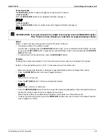
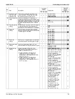
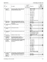
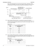
[2-27]: Night-time low noise operation stop time
Default value: 3.
This setting is used in conjunction with setting [2-22].
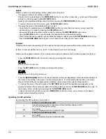
[2-28]: Power transistor check mode
To evaluate the output of the power transistors. Use this function in case error code is displayed related
to defective inverter PCB or inverter compressor is locked.
Default value: 0. Power transistor check mode is not active.
Field setting 1: Power transistor check mode is active.
Function:
Inverter PCB gives output of 10 Hz in sequence by all 6 transistors. Remove the U/V/W terminals of
the inverter compressor, and connect to the inverter checker module. If all 6 LEDs blink, the transistors
switch correctly.
When the power transistor check mode is interrupted, after internal power circuit is disconnected on
the inverter PCB, 2 LEDs will light up to indicate discharge of the DC voltage. Wait till the LEDs are
OFF before returning fasten terminals back to the compressor terminals.
Minimum requirements to refer to the result on the inverter checker module:
All 3 phases and neutral are available, and
Inverter PCB control is active. Check if the green LED “HAP” on the inverter PCBs are blinking normal
(approx. 1/ second). If LEDs are OFF, need to exit the “standby mode” of the inverter:
Disconnect and reconnect power supply control PCB, or
Forced thermostat ON condition, or
Make shortly set 2-6-1 (forced thermostat ON indoor), or 2-20-1 (manual refrigerant charge).
Once the LED is blinking on the inverter PCB, change related setting immediately back to set 0 to
deactivate related function.
Diode module generates the required 260 VDC at REYQ-XATJU, 600 VDC at REYQ-XAYDU or
750 VDC at REYQ-XAYCU.
Cautions:
In case there is more than 1 compressor in a system (outdoor is multi outdoor configuration) all
compressor inverter PCBs will perform the power transistor check. In such case, disconnect U/V/W
fasten terminals on all compressors. Avoid accidental touch of fasten terminals to short circuit or earth
leak to casing.
To stop the power transistor check mode, change setting to default 2-28-0.
Output to U/V/W will also stop when outdoor unit main PCB decides standby mode of inverter circuit.
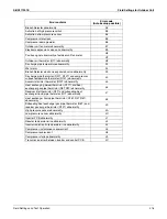
Value
[2-27]
Stop time automatic night-time low noise
operation (approximately)
1
About 6:00 AM
2
About 7:00 AM
3 (default)
About 8:00 AM
Summary of Contents for REYQ-XA
Page 1: ...Service Manual SiUS371901E REYQ72 456XATJU REYQ72 456XAYDU REYQ72 432XAYCU Heat Recovery 60 Hz...
Page 415: ...SiUS371901E Wiring Diagrams Appendix 402 REYQ144 168XATJU 2D119206A...
Page 416: ...Wiring Diagrams SiUS371901E 403 Appendix REYQ72 96 120XAYDU 2D119207B...
Page 417: ...SiUS371901E Wiring Diagrams Appendix 404 REYQ144 168XAYDU 2D119208B...
Page 418: ...Wiring Diagrams SiUS371901E 405 Appendix REYQ72 96 120 144 168XAYCU 2D119209A...
Page 421: ...SiUS371901E Wiring Diagrams Appendix 408 FXZQ05 07 09 12 15 18TAVJU 3D110443A...
Page 423: ...SiUS371901E Wiring Diagrams Appendix 410 FXEQ07 09 12 15 18 24PVJU 3D098557A...
Page 425: ...SiUS371901E Wiring Diagrams Appendix 412 FXSQ05 07 09 12 15 18 24 30 36 48 54TAVJU C 3D110467C...
Page 426: ...Wiring Diagrams SiUS371901E 413 Appendix FXMQ07 09 12 15 18 24 30 36 48 54PBVJU 3D093209B...
Page 428: ...Wiring Diagrams SiUS371901E 415 Appendix FXHQ12 24 36MVJU 3D048116C...
Page 429: ...SiUS371901E Wiring Diagrams Appendix 416 FXAQ07 09 12 18 24PVJU C 3D075354D...
Page 435: ...SiUS371901E Wiring Diagrams Appendix 422 VAM1200GVJU 3D073270D...
Page 437: ...SiUS371901E Wiring Diagrams Appendix 424 1 4 2 Multi Branch Selector Unit BS4Q54TVJ 3D089123B...
Page 438: ...Wiring Diagrams SiUS371901E 425 Appendix BS6 8Q54TVJ 2D089122B...
Page 439: ...SiUS371901E Wiring Diagrams Appendix 426 BS10 12Q54TVJ 2D089121B...
Page 440: ...Revision History Month Year Version Revised contents 04 2019 SiUS371901E First edition...


