SiUS371901E
Symptom-based Troubleshooting
Service Diagnosis
228
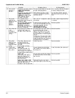
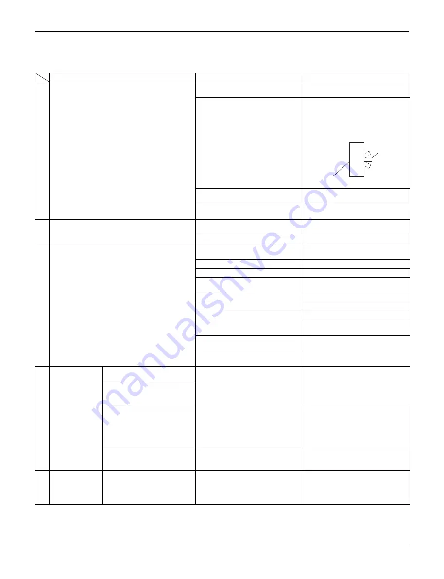
1. Symptom-based Troubleshooting
1.1
Indoor Unit Overall
Symptom
Supposed Cause
Countermeasure
1
The system does not start operation at all.
Blowout of fuse (s)
Turn OFF the power supply and
then replace the fuse (s).
Cutout of breaker (s)
• If the knob of any breaker is in its
OFF position, turn ON the power
supply.
• If the knob of any circuit breaker
is in its tripped position, do not
turn ON the power supply.
Power failure
After the power failure is reset,
restart the system.
The connector loose or not fully
plugged in
Turn off the power supply to verify
the connection of the connector.
2
The system starts operation but makes an
immediate stop.
Blocked air inlet or outlet of indoor
or outdoor unit
Remove obstacle (s).
Clogged air filter (s)
Clean the air filter (s).
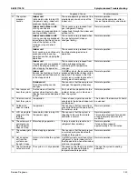
3
The system does not cool or heat air well.
Blocked air inlet or outlet of indoor
or outdoor unit
Remove obstacle (s).
Clogged air filter (s)
Clean the air filter (s).
Enclosed outdoor unit (s)
Remove the enclosure.
Improper set temperature
Set the temperature to a proper
degree.
Airflow rate set to LOW
Set it to a proper airflow rate.
Improper direction of air diffusion
Set it to a proper direction.
Open window (s) or door (s)
Shut it tightly.
[In cooling] Direct sunlight received
Hang curtains or shades on
windows.
[In cooling] Too many persons staying in a
room
The model must be selected to
match the air conditioning load.
[In cooling] Too many heat sources (e.g. OA
equipment) located in a room
4
The system does
not operate.
The system stops and
immediately restarts operation.
If the operation lamp on the remote
controller turns ON, the system will
be normal. These symptoms
indicate that the system is
controlled so as not to put
unreasonable loads on the system.
Normal operation. The system will
automatically start operation after a
lapse of five minutes.
Pressing the temperature
setting button immediately
resets the system.
The remote controller displays
UNDER CENTRALIZED
CONTROL
, which blinks for a
period of several seconds
when the
OPERATION
button
is depressed.
The system is controlled with
centralized controller. Blinking
display indicates that the system
cannot be operated using the
remote controller.
Operate the system using the
COOL/HEAT central remote
controller.
The system stops immediately
after turning ON the power
supply.
The system is in preparation mode
of microcomputer operation.
Wait for a period of approximately
one minute.
5
The system
makes
intermittent
stops.
The remote controller displays
error codes
U4
or
U5
, and the
system stops but restarts after
a lapse of several minutes.
The system stops due to an
interruption in communication
between units caused by electrical
noises coming from equipment
other than air conditioners.
Remove causes of electrical
noises.
If these causes are removed, the
system will automatically restart
operation.
ON
Knob
Tripped
OFF
Circuit breaker
Summary of Contents for REYQ-XA
Page 1: ...Service Manual SiUS371901E REYQ72 456XATJU REYQ72 456XAYDU REYQ72 432XAYCU Heat Recovery 60 Hz...
Page 415: ...SiUS371901E Wiring Diagrams Appendix 402 REYQ144 168XATJU 2D119206A...
Page 416: ...Wiring Diagrams SiUS371901E 403 Appendix REYQ72 96 120XAYDU 2D119207B...
Page 417: ...SiUS371901E Wiring Diagrams Appendix 404 REYQ144 168XAYDU 2D119208B...
Page 418: ...Wiring Diagrams SiUS371901E 405 Appendix REYQ72 96 120 144 168XAYCU 2D119209A...
Page 421: ...SiUS371901E Wiring Diagrams Appendix 408 FXZQ05 07 09 12 15 18TAVJU 3D110443A...
Page 423: ...SiUS371901E Wiring Diagrams Appendix 410 FXEQ07 09 12 15 18 24PVJU 3D098557A...
Page 425: ...SiUS371901E Wiring Diagrams Appendix 412 FXSQ05 07 09 12 15 18 24 30 36 48 54TAVJU C 3D110467C...
Page 426: ...Wiring Diagrams SiUS371901E 413 Appendix FXMQ07 09 12 15 18 24 30 36 48 54PBVJU 3D093209B...
Page 428: ...Wiring Diagrams SiUS371901E 415 Appendix FXHQ12 24 36MVJU 3D048116C...
Page 429: ...SiUS371901E Wiring Diagrams Appendix 416 FXAQ07 09 12 18 24PVJU C 3D075354D...
Page 435: ...SiUS371901E Wiring Diagrams Appendix 422 VAM1200GVJU 3D073270D...
Page 437: ...SiUS371901E Wiring Diagrams Appendix 424 1 4 2 Multi Branch Selector Unit BS4Q54TVJ 3D089123B...
Page 438: ...Wiring Diagrams SiUS371901E 425 Appendix BS6 8Q54TVJ 2D089122B...
Page 439: ...SiUS371901E Wiring Diagrams Appendix 426 BS10 12Q54TVJ 2D089121B...
Page 440: ...Revision History Month Year Version Revised contents 04 2019 SiUS371901E First edition...

