Troubleshooting by Error Code
SiUS371901E
237
Service Diagnosis
Notes:
∗
1. The system can keep operating, however, be sure to check and repair.
∗
2. The system may or may not continue operation depending on the conditions.
Outdoor Unit
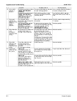
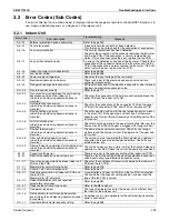
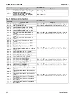
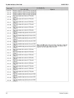
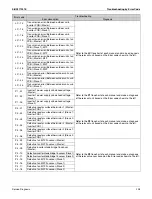
H3
l
Harness abnormality (between outdoor unit main PCB and inverter PCB)
H7
l
Outdoor fan motor signal abnormality
Outdoor fan PCB abnormality
H9
l
Outdoor air thermistor (R1T) abnormality
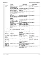
J3
l
Discharge pipe thermistor (R21T) abnormality
Compressor body thermistor (R14T) abnormality
J5
l
Compressor suction thermistor (R12T) abnormality
Suction pipe thermistor (R10T) abnormality
J6
l
Heat exchanger deicer thermistor (R11T) abnormality
Heat exchanger gas pipe thermistor (R8T, R9T) abnormality
J7
l
Receiver inlet thermistor (R3T) abnormality
Subcooling heat exchanger liquid pipe thermistor (R7T) abnormality
Subcooling injection thermistor (R16T) abnormality
J8
l
Heat exchanger liquid pipe thermistor (R4T, R5T) abnormality
J9
l
Subcooling heat exchanger gas pipe thermistor (R6T) abnormality
Receiver gas purge thermistor (R13T) abnormality
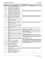
JA
l
High pressure sensor abnormality
JC
l
Low pressure sensor abnormality
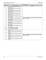
L1
l
Inverter PCB abnormality
L2
l
Momentary power failure during test operation
L3
l
Reactor temperature rise abnormality
L4
l
Inverter radiation fin temperature rise abnormality
L5
l
Compressor instantaneous overcurrent
L8
l
Compressor overcurrent
L9
l
Compressor startup abnormality
LC
l
Transmission error between inverter PCB and outdoor unit main PCB
P1
l
Power supply voltage imbalance
P3
l
Reactor surface thermistor abnormality
P4 (
∗
1)
l
Inverter radiation fin temperature abnormality
PJ
l
Field setting after replacing outdoor unit main PCB abnormality or combination
of PCB abnormality
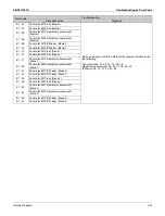
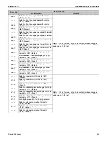
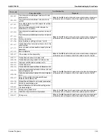
System
U0 (
∗
1)
k
Refrigerant shortage
U1
l
Reverse phase, open phase
U2
l
Power supply insufficient or instantaneous abnormality
U3
l
Check operation not executed
U4
l
Transmission error between indoor units and outdoor units, open phase in
power supply wiring
U5
l
Transmission error between remote controller and indoor unit
U7
l
Transmission error between outdoor units
U8
l
Transmission error between main and sub remote controllers
U9
l
Transmission error between indoor units and outdoor units in the same system
UA
l
Improper combination of indoor, Branch Selector and outdoor units
Incorrect gas furnace connecting number
Incorrect electric heater capacity setting
UC (
∗
1)
k
Address duplication of centralized controller
UE
l
Transmission error between centralized controller and indoor unit
UF
l
System not set yet
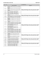
UH
l
System abnormality, refrigerant system address undefined
Climate Talk communication system combination error (before initial setting for
communication completes)
Climate Talk communication system combination error (after initial setting for
communication completes)
k
: ON
h
: OFF
l
: Blink
Error code
Operation
lamp
Descriptions
Reference
page
Summary of Contents for REYQ-XA
Page 1: ...Service Manual SiUS371901E REYQ72 456XATJU REYQ72 456XAYDU REYQ72 432XAYCU Heat Recovery 60 Hz...
Page 415: ...SiUS371901E Wiring Diagrams Appendix 402 REYQ144 168XATJU 2D119206A...
Page 416: ...Wiring Diagrams SiUS371901E 403 Appendix REYQ72 96 120XAYDU 2D119207B...
Page 417: ...SiUS371901E Wiring Diagrams Appendix 404 REYQ144 168XAYDU 2D119208B...
Page 418: ...Wiring Diagrams SiUS371901E 405 Appendix REYQ72 96 120 144 168XAYCU 2D119209A...
Page 421: ...SiUS371901E Wiring Diagrams Appendix 408 FXZQ05 07 09 12 15 18TAVJU 3D110443A...
Page 423: ...SiUS371901E Wiring Diagrams Appendix 410 FXEQ07 09 12 15 18 24PVJU 3D098557A...
Page 425: ...SiUS371901E Wiring Diagrams Appendix 412 FXSQ05 07 09 12 15 18 24 30 36 48 54TAVJU C 3D110467C...
Page 426: ...Wiring Diagrams SiUS371901E 413 Appendix FXMQ07 09 12 15 18 24 30 36 48 54PBVJU 3D093209B...
Page 428: ...Wiring Diagrams SiUS371901E 415 Appendix FXHQ12 24 36MVJU 3D048116C...
Page 429: ...SiUS371901E Wiring Diagrams Appendix 416 FXAQ07 09 12 18 24PVJU C 3D075354D...
Page 435: ...SiUS371901E Wiring Diagrams Appendix 422 VAM1200GVJU 3D073270D...
Page 437: ...SiUS371901E Wiring Diagrams Appendix 424 1 4 2 Multi Branch Selector Unit BS4Q54TVJ 3D089123B...
Page 438: ...Wiring Diagrams SiUS371901E 425 Appendix BS6 8Q54TVJ 2D089122B...
Page 439: ...SiUS371901E Wiring Diagrams Appendix 426 BS10 12Q54TVJ 2D089121B...
Page 440: ...Revision History Month Year Version Revised contents 04 2019 SiUS371901E First edition...

