SiUS371901E
Outline of Control (Indoor Unit)
Functions and Control
142
9.4
Thermostat Control
9.4.1 Without Optional Infrared Presence/Floor Sensor
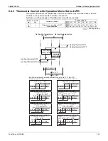
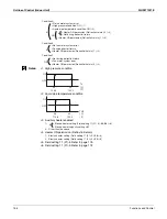
Whether the thermostat is turned ON or OFF is determined by the difference between the remote
controller set temperature and the actual detected room temperature (
∗
1).
Normal operation
· Cooling operation
· Heating operation
Dry operation
· When Tro < 24.5°C (76.1°F)
· When Tro
≥
24.5°C (76.1°F)
FXTQ-TA, CXTQ-TA only
If the field setting 14 (24)-5 is set to
02
, Tro will be the same as the cooling set temperature.
∆
T : Room temperature – Remote controller set temperature
Tro : Room temperature at the start of dry operation
Tr : Room temperature
∗
1: The thermistor for room temperature detection depends on the field setting 10 (20)-2.
Thermostat OFF
Normal operation
(Thermostat ON)
∆
T
≤
–1.0˚C (–1.8˚F)
∆
T
≥ +
1.0˚C (
+
1.8˚F)
Thermostat OFF
Normal operation
(Thermostat ON)
∆
T
≥ +
1.0˚C (
+
1.8˚F)
∆
T
≤
–1.0˚C (–1.8˚F)
Thermostat OFF
Dry operation
Tr
<
Tro – 1.0˚C (–1.8˚F)
Tr
>
Tro + 1.0˚C (
+
1.8˚F)
Thermostat OFF
Dry operation
Tr
<
Tro – 1.5˚C (–2.7˚F)
Tr
>
Tro + 0.5˚C (+0.9˚F)
Thermostat OFF
Dry operation
Tr < Tro –1.0˚C (–1.8˚F)
Tr
>
Tro + 1.0˚C (+1.8˚F)
Summary of Contents for REYQ-XA
Page 1: ...Service Manual SiUS371901E REYQ72 456XATJU REYQ72 456XAYDU REYQ72 432XAYCU Heat Recovery 60 Hz...
Page 415: ...SiUS371901E Wiring Diagrams Appendix 402 REYQ144 168XATJU 2D119206A...
Page 416: ...Wiring Diagrams SiUS371901E 403 Appendix REYQ72 96 120XAYDU 2D119207B...
Page 417: ...SiUS371901E Wiring Diagrams Appendix 404 REYQ144 168XAYDU 2D119208B...
Page 418: ...Wiring Diagrams SiUS371901E 405 Appendix REYQ72 96 120 144 168XAYCU 2D119209A...
Page 421: ...SiUS371901E Wiring Diagrams Appendix 408 FXZQ05 07 09 12 15 18TAVJU 3D110443A...
Page 423: ...SiUS371901E Wiring Diagrams Appendix 410 FXEQ07 09 12 15 18 24PVJU 3D098557A...
Page 425: ...SiUS371901E Wiring Diagrams Appendix 412 FXSQ05 07 09 12 15 18 24 30 36 48 54TAVJU C 3D110467C...
Page 426: ...Wiring Diagrams SiUS371901E 413 Appendix FXMQ07 09 12 15 18 24 30 36 48 54PBVJU 3D093209B...
Page 428: ...Wiring Diagrams SiUS371901E 415 Appendix FXHQ12 24 36MVJU 3D048116C...
Page 429: ...SiUS371901E Wiring Diagrams Appendix 416 FXAQ07 09 12 18 24PVJU C 3D075354D...
Page 435: ...SiUS371901E Wiring Diagrams Appendix 422 VAM1200GVJU 3D073270D...
Page 437: ...SiUS371901E Wiring Diagrams Appendix 424 1 4 2 Multi Branch Selector Unit BS4Q54TVJ 3D089123B...
Page 438: ...Wiring Diagrams SiUS371901E 425 Appendix BS6 8Q54TVJ 2D089122B...
Page 439: ...SiUS371901E Wiring Diagrams Appendix 426 BS10 12Q54TVJ 2D089121B...
Page 440: ...Revision History Month Year Version Revised contents 04 2019 SiUS371901E First edition...

