SiUS371901E
Outline of Control (Indoor Unit)
Functions and Control
158
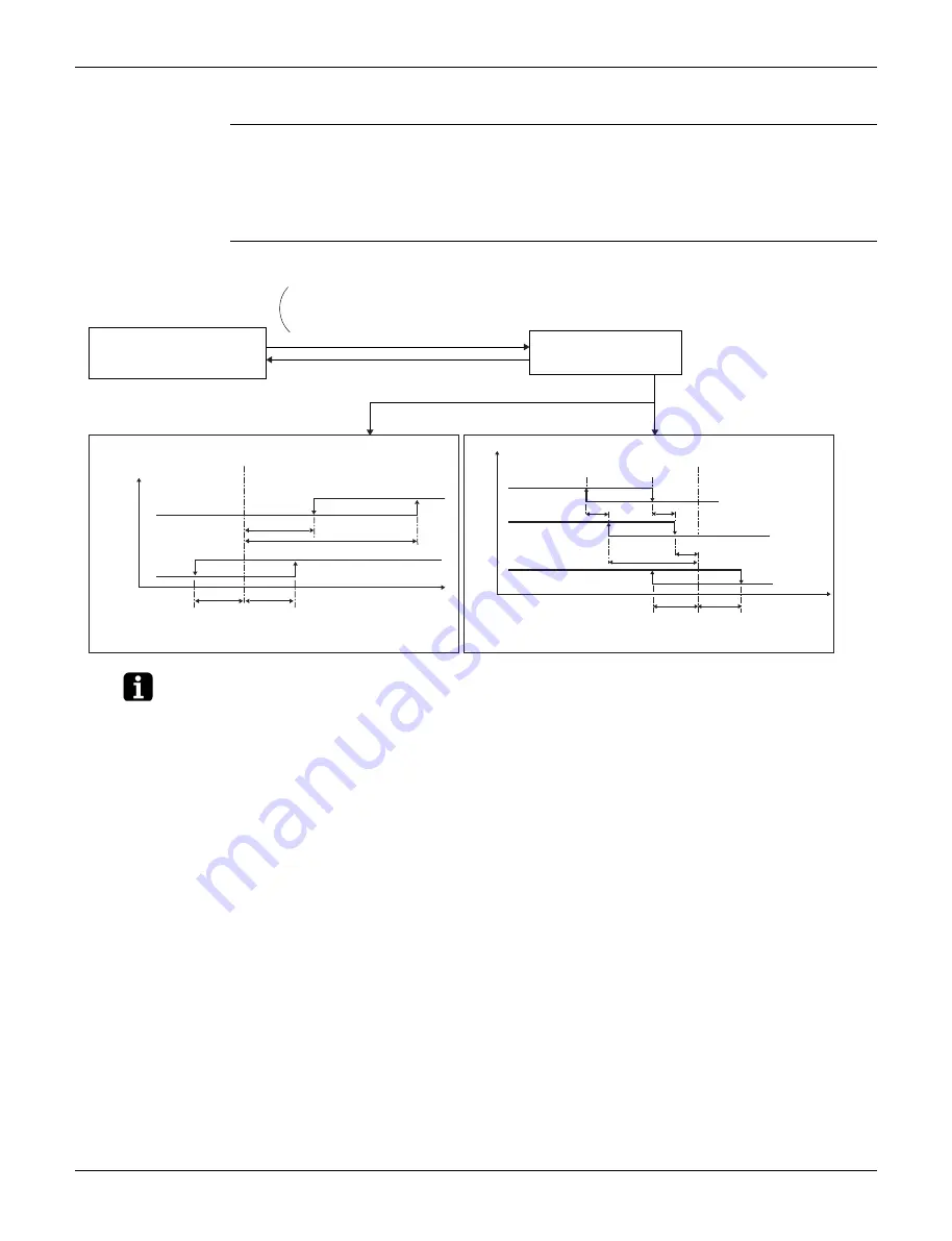
9.14 3-Step Thermostat Processing (FXTQ-TA Models)
Outline
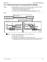
The thermostat ON/OFF for the indoor unit is controlled in accordance with [Thermostat step 1].
The heater ON/OFF operation during heating is controlled as follows.
Thermostat step 2, 3: Auxiliary electric heater control
Thermostat step 1, 2: Heat pump lockout control
For more details of the heater, refer to
Heater
Control (FXTQ-TA Models)
Detail
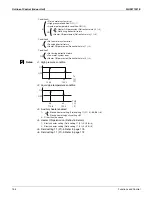
Notes:
∗
1.
S
value varies automatically based on the room temperature trend.
∗
2. Ton +
S
> –
B
(°C), Toff +
S
<
A
(°C)
∗
3. For parameters, refer to page 173.
∗
4.
A
and
B
values vary automatically based on the field setting 12 (22)-2.
∗
5. If, directly after a change in conditions, it is such that the thermostat could be either ON or OFF
(controlled temperature is within ranges
A
and
B
), the thermostat will be switched to ON.
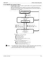
&
•
No errors (except errors in which the system keeps operating)
has occurred.
•
Remote controller ON
• Thermostat step 1: OFF
• Thermostat step 2: OFF
• Thermostat step 3: OFF
Elimination conditions of the above
Perform the processing in
the following chart. (
∗
5)
(1) Cooling
(2) Heating
Thermostat step 2
Thermostat step 1
ON
OFF
ON
OFF
2+
S
(
∗
1)
4+
S
(
∗
1)
A
(
∗
4)
B
(
∗
4)
Controlled temperature
(Tcon)(˚C)
Set temperature (Ts’)
Thermostat step 3
Thermostat step 2
Thermostat step 1
ON
OFF
ON
OFF
ON
OFF
1.5
1.5
Toff+
S
(
∗
1,2,3)
Ton+
S
(
∗
1,2,3)
A
(
∗
4)
B
(
∗
4)
Set temperature (Ts’)
Controlled
temperature
(Tcon)(˚C)
Summary of Contents for REYQ72-456XATJU
Page 415: ...SiUS371901E Wiring Diagrams Appendix 402 REYQ144 168XATJU 2D119206A ...
Page 416: ...Wiring Diagrams SiUS371901E 403 Appendix REYQ72 96 120XAYDU 2D119207B ...
Page 417: ...SiUS371901E Wiring Diagrams Appendix 404 REYQ144 168XAYDU 2D119208B ...
Page 418: ...Wiring Diagrams SiUS371901E 405 Appendix REYQ72 96 120 144 168XAYCU 2D119209A ...
Page 421: ...SiUS371901E Wiring Diagrams Appendix 408 FXZQ05 07 09 12 15 18TAVJU 3D110443A ...
Page 423: ...SiUS371901E Wiring Diagrams Appendix 410 FXEQ07 09 12 15 18 24PVJU 3D098557A ...
Page 426: ...Wiring Diagrams SiUS371901E 413 Appendix FXMQ07 09 12 15 18 24 30 36 48 54PBVJU 3D093209B ...
Page 428: ...Wiring Diagrams SiUS371901E 415 Appendix FXHQ12 24 36MVJU 3D048116C ...
Page 429: ...SiUS371901E Wiring Diagrams Appendix 416 FXAQ07 09 12 18 24PVJU C 3D075354D ...
Page 435: ...SiUS371901E Wiring Diagrams Appendix 422 VAM1200GVJU 3D073270D ...
Page 437: ...SiUS371901E Wiring Diagrams Appendix 424 1 4 2 Multi Branch Selector Unit BS4Q54TVJ 3D089123B ...
Page 438: ...Wiring Diagrams SiUS371901E 425 Appendix BS6 8Q54TVJ 2D089122B ...
Page 439: ...SiUS371901E Wiring Diagrams Appendix 426 BS10 12Q54TVJ 2D089121B ...
Page 440: ...Revision History Month Year Version Revised contents 04 2019 SiUS371901E First edition ...


