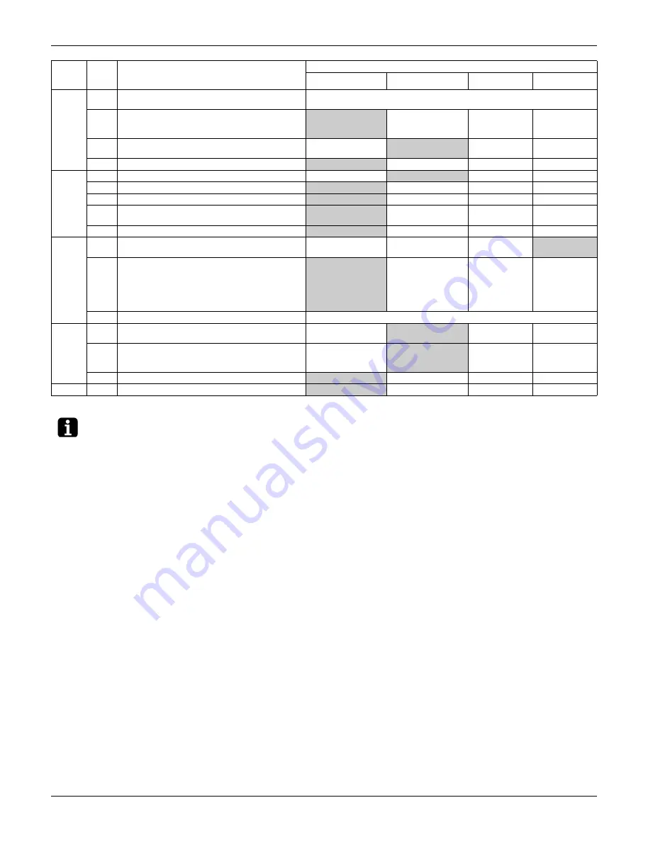
Field Settings for Indoor Unit
SiUS371901E
167
Field Settings and Test Operation
Notes :
1. Settings are made simultaneously for the entire group, however, if you select the mode No. inside
parentheses, you can also set by each individual unit. Setting changes however cannot be checked except in
the individual mode for those in parentheses.
∗
2. The mode numbers inside parentheses cannot be used by wireless remote controllers, so they cannot be set
individually. Setting changes also cannot be checked.
3. Do not make settings other than those described above. Nothing is displayed for functions the indoor unit is
not equipped with.
4.
88
or
Checking the connection. Please stand by.
may be displayed to indicate the remote controller is
resetting when returning to the normal mode.
∗
5. If the setting mode to “Equipped”, energy recovery ventilator fan conducts the fan residual operation by
linking to indoor unit.
∗
6. Only for FXTQ-TA models
∗
7. Only for FXDQ-M, FXTQ-TA, CXTQ-TA models
∗
8. If the airflow setting when thermostat is OFF is set to OFF (12 (22)-3-03, 12 (22)-6-03), the air in the indoor
unit will be stagnant and suction air thermistor may not detect room temperature correctly, resulting in
problems that thermostat will not be ON easily.
Use optional remote sensor in such conditions, or set the field setting 10 (20)-2 to
03
(only remote controller
thermistor).
∗
9. Only for FXFQ-T, FXZQ-TA, and FXUQ-P sensing models
∗
10.Only for CXTQ-TA models
∗
11.Only for FXTQ-TA and CXTQ-TA models
∗
12.Only for FXDQ-M models
∗
13.Only for FXEQ-P models
Mode
No.
(
∗
2)
First
Code
No.
Setting Contents
Second Code No.
01
02
03
04
14 (24)
4 (*11)
Optional kit setting (UV lamp + humi
economizer)
Refer to page 181 for details.
5 (*11) Residential dry
Set temperature:
room temperature
Set temperature:
same as cooling set
temperature
—
—
9 (
∗
13) Mold proof operation setting
—
Standard
For high
humidity areas
—
11 (
∗
10) Gas furnace test mode
OFF
Low heat
High heat
—
15 (25)
0
Drain pump operation settings
—
ON
OFF
—
1
Humidification when heating thermostat is OFF
Not equipped
Equipped
—
—
2 (
∗
5) Setting of direct duct connection
Not equipped
Equipped
—
—
3
Interlocked operation between humidifier and
drain pump
Not interlocked
Interlocked
—
—
5
Individual setting of ventilation
— (Normal)
Individual
—
—
1b
4
Display of error codes on the remote controller
—
Two-digit display
—
Four-digit
display
12
Key-lock pattern settings
No operation
allowed (Cancel
procedure is
displayed.)
No operation
allowed (Cancel
procedure is not
displayed.)
No menu
operation is
allowed
(Cancel
procedure is
displayed.)
No menu
operation is
allowed any
time.
14
Setting "restricted / permitted" of airflow block
Refer to page 183 for details.
1c
0
Room temperature display
Room temperature
is not displayed
Room temperature
is displayed
—
—
1
Thermistor sensor for auto changeover and
setback control by the remote controller
Utilize the return air
thermistor
Utilize the remote
controller
thermistor
—
—
3
Access permission level setting
Level 2
Level 3
—
—
1e
2
Setback availability
N/A
Heat only
Cool only
Cool/heat
Summary of Contents for REYQ72-456XATJU
Page 415: ...SiUS371901E Wiring Diagrams Appendix 402 REYQ144 168XATJU 2D119206A ...
Page 416: ...Wiring Diagrams SiUS371901E 403 Appendix REYQ72 96 120XAYDU 2D119207B ...
Page 417: ...SiUS371901E Wiring Diagrams Appendix 404 REYQ144 168XAYDU 2D119208B ...
Page 418: ...Wiring Diagrams SiUS371901E 405 Appendix REYQ72 96 120 144 168XAYCU 2D119209A ...
Page 421: ...SiUS371901E Wiring Diagrams Appendix 408 FXZQ05 07 09 12 15 18TAVJU 3D110443A ...
Page 423: ...SiUS371901E Wiring Diagrams Appendix 410 FXEQ07 09 12 15 18 24PVJU 3D098557A ...
Page 426: ...Wiring Diagrams SiUS371901E 413 Appendix FXMQ07 09 12 15 18 24 30 36 48 54PBVJU 3D093209B ...
Page 428: ...Wiring Diagrams SiUS371901E 415 Appendix FXHQ12 24 36MVJU 3D048116C ...
Page 429: ...SiUS371901E Wiring Diagrams Appendix 416 FXAQ07 09 12 18 24PVJU C 3D075354D ...
Page 435: ...SiUS371901E Wiring Diagrams Appendix 422 VAM1200GVJU 3D073270D ...
Page 437: ...SiUS371901E Wiring Diagrams Appendix 424 1 4 2 Multi Branch Selector Unit BS4Q54TVJ 3D089123B ...
Page 438: ...Wiring Diagrams SiUS371901E 425 Appendix BS6 8Q54TVJ 2D089122B ...
Page 439: ...SiUS371901E Wiring Diagrams Appendix 426 BS10 12Q54TVJ 2D089121B ...
Page 440: ...Revision History Month Year Version Revised contents 04 2019 SiUS371901E First edition ...

