SiUS371901E
Field Settings for Outdoor Unit
Field Settings and Test Operation
204
[2-20]: Additional refrigerant charge
In order to add the additional refrigerant charge amount following setting should be applied.
Default value: 0
To activate this function, change [2-20] to 1.
To stop the additional refrigerant charge operation (when the required additional refrigerant amount is
charged), press the
RETURN (BS3)
button. If this function was not aborted by pressing the
RETURN
(BS3)
button, the unit will stop its operation after 30 minutes.
If 30 minutes was not sufficient to add the needed refrigerant amount, the function can be reactivated by
changing the field setting again.
[2-21]: Refrigerant recovery/vacuuming mode
In order to achieve a free pathway to recovering refrigerant out of the system or to remove residual
substances or to vacuum the system it is necessary to apply a setting which will open required valves in
the refrigerant circuit so the recovering of refrigerant or vacuuming process can be done properly.
Default value: 0
To activate this function, change [2-21] to 1.
To stop the refrigerant recovery/vacuuming mode, press the
RETURN (BS3)
button. If the
RETURN
(BS3)
button is not pressed, the system will remain in refrigerant recovery/vacuuming mode.
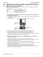
[2-22]: Automatic night-time low noise setting and level during night-time
By changing this setting, you can activate the automatic night-time low noise operation function of the
unit and define the level of operation. Depending on the chosen level, the noise level will be lowered
(3: Level 3 < 2: Level 2 < 1: Level 1).
The start and stop moments for this function are defined under setting [2-26] and [2-27].
Default value: 0
Change [2-22] to 1, 2 or 3 in function of required level.
[2-25]: Night-time low noise operation level via the external control adaptor
If the system needs to run under night-time low noise operation conditions when an external signal is
sent to the unit, this setting defines the level of night-time low noise that will be applied
(3: Level 3 < 2: Level 2 < 1: Level 1).
This setting will only be effective when the optional external control adaptor (DTA104A61/62) is installed
and the setting [2-12] was activated.
Default value: 2
Change [2-25] to 1, 2 or 3 in function of required level.
[2-26]: Night-time low noise operation start time
Change [2-26] to 1, 2 or 3 in function of required timing.
Default value: 2.
This setting is used in conjunction with setting [2-22].
Value
[2-26]
Start time automatic night-time low noise
operation (approximately)
1
About 8:00 PM
2 (default)
About 10:00 PM
3
About 12:00 AM
Summary of Contents for REYQ72-456XATJU
Page 415: ...SiUS371901E Wiring Diagrams Appendix 402 REYQ144 168XATJU 2D119206A ...
Page 416: ...Wiring Diagrams SiUS371901E 403 Appendix REYQ72 96 120XAYDU 2D119207B ...
Page 417: ...SiUS371901E Wiring Diagrams Appendix 404 REYQ144 168XAYDU 2D119208B ...
Page 418: ...Wiring Diagrams SiUS371901E 405 Appendix REYQ72 96 120 144 168XAYCU 2D119209A ...
Page 421: ...SiUS371901E Wiring Diagrams Appendix 408 FXZQ05 07 09 12 15 18TAVJU 3D110443A ...
Page 423: ...SiUS371901E Wiring Diagrams Appendix 410 FXEQ07 09 12 15 18 24PVJU 3D098557A ...
Page 426: ...Wiring Diagrams SiUS371901E 413 Appendix FXMQ07 09 12 15 18 24 30 36 48 54PBVJU 3D093209B ...
Page 428: ...Wiring Diagrams SiUS371901E 415 Appendix FXHQ12 24 36MVJU 3D048116C ...
Page 429: ...SiUS371901E Wiring Diagrams Appendix 416 FXAQ07 09 12 18 24PVJU C 3D075354D ...
Page 435: ...SiUS371901E Wiring Diagrams Appendix 422 VAM1200GVJU 3D073270D ...
Page 437: ...SiUS371901E Wiring Diagrams Appendix 424 1 4 2 Multi Branch Selector Unit BS4Q54TVJ 3D089123B ...
Page 438: ...Wiring Diagrams SiUS371901E 425 Appendix BS6 8Q54TVJ 2D089122B ...
Page 439: ...SiUS371901E Wiring Diagrams Appendix 426 BS10 12Q54TVJ 2D089121B ...
Page 440: ...Revision History Month Year Version Revised contents 04 2019 SiUS371901E First edition ...


